【Notification of Manufacturer Change for Panasonic Industrial Devices SUNX Products and Panasonic Industrial Devices SUNX Tatsuno Products】
From April 1, 2024, the terms "Panasonic Industrial Devices SUNX Co., Ltd." and "Panasonic Industrial Devices SUNX Tatsuno Co., Ltd."
in this page and in the manuals and other documents to be downloaded will all be replaced with "Panasonic Industry Co., Ltd." and applied accordingly.

 Business
> Industrial Devices
> Automation Controls Top
> FA Sensors & Components
> Sensors
> Fiber Sensors
> Manually Set Fiber Sensor FX-311
> Cautions For Use
Business
> Industrial Devices
> Automation Controls Top
> FA Sensors & Components
> Sensors
> Fiber Sensors
> Manually Set Fiber Sensor FX-311
> Cautions For Use
Manually Set Fiber Sensor FX-311
|
Cautions For Use
- Never use this product as a sensing device for personnel protection.
- In case of using sensing devices for personnel protection, use products which meet laws and standards, such as OSHA, ANSI or IEC etc., for personnel protection applicable in each region or country.
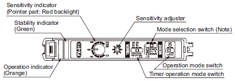
Part description
|
Amplifier of cascading
| ・ | Make sure that the power supply is off while adding or removing the amplifiers. |
|---|---|
| ・ | Make sure to check the allowable ambient temperature, as it depends on the number of amplifiers connected in cascade. |
| ・ | In case two, or more, amplifiers are connected in cascade, make sure to mount them on a DIN rail. |
| ・ | When the amplifiers move on the DIN rail depending on the attaching condition, fitting them between the optional end plates (MS-DIN-E) mounted at the two ends. |
| ・ | When connecting in cascade, mount the amplifiers close to each other, fitting them between the optional end plates (MS-DIN-E) mounted at the two ends. |
| ・ | Up to maximum 15 amplifiers can be added (total 16 amplifiers connected in cascade.) |
| ・ | When connecting more than two amplifiers in cascade, use the sub cable (CN-71-C□) as the quick-connection cable for the second amplifier onwards. |
| ・ | The settings other than the interference prevention function cannot be transmitted between this product and other digital fiber amplifiers. Therefore, in case both models of amplifiers are mounted in cascade, be sure to mount identical models together. For more details, refer to "Cautions on sensor connection in cascade". |
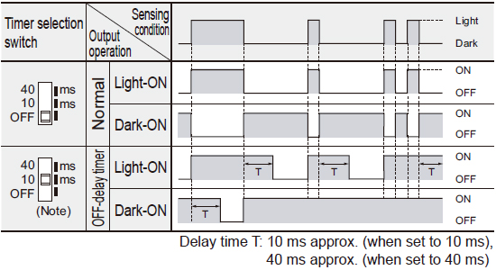
Timer function
- This product incorporates an OFF-delay timer function. The delay time can be selected as either 10 ms. approx. or 40 ms. approx. with the timer selection switch. Since the output is extended by a fixed period, it is useful when the connected device has a slow response time or when small objects are being sensed and the output signal width is small.
|
Automatic interference prevention function
- This product incorporates an automatic interference prevention function. If the amplifiers are mounted in cascade, since a different emission timing is automatically set for up to 4 amplifiers, up to 4 sets of fibers can be mounted closely.
Further, even if the amplifiers are mounted closely along with the digital fiber sensor FX-300 series, the interference prevention function works. However, in case both models of amplifiers are mounted in cascade, mount identical models together.
Wiring
- Make sure that the power supply is off while wiring.
- Verify that the supply voltage variation is within the rating.
- Take care that if a voltage exceeding the rated range is applied, or if an AC power supply is directly connected, the product may get burnt or damaged.
- If power is supplied from a commercial switching regulator, ensure that the frame ground (F.G.) terminal of the power supply is connected to an actual ground.
- In case noise generating equipment (switching regulator, inverter motor, etc.) is used in the vicinity of this product, connect the frame ground (F.G.) terminal of the equipment to an actual ground.
- Take care that short circuit of the load wrong wiring may burn or damage the product.
- Do not run the wires together with high-voltage lines or power lines or put them in the same raceway. This can cause malfunction due to induction.
- Make sure to use an isolation transformer for the DC power supply. If an autotransformer (single winding transformer) is used, this product or the power supply may get damaged.
- Make sure to use the optional quick-connection cable for the connection of the amplifier. Extension up to total 100 m 328.084 ft is possible with 0.3 mm2, or more, cable.
However, in order to reduce noise, make the wiring as short as possible.
Operation procedure
- For FX-311(P), the most suitable sensing mode can be selected according to the application from LONG (long range distance), STD (standard) or S-D (reduced intensity). Furthermore, for FX-311B(P) and FX-311G(P), the sensing mode can be selected from LONG (long range distance), STD (standard) or FAST (high speed sensing).
| Mode selection switch | Applications | Response time |
|
|---|---|---|---|
| FX-311(P) | FX-311B(P)/311G(P) | ||
 |
 |
Used in case long distance sensing is required. (However, the response time is longer than in STD mode.) |
2 ms |
 |
 |
Used for general sensing application. | 250 μs |
| - |  |
Used in case high speed sensing is required. | 150 μs |
 |
- | Since the emitted light amount is restricted in this mode, it is suitable for delicate sensing, such as when the received light is saturated due to too short a sensing distance or when detecting translucent objects, etc. | 250 μs |
| Note: | Make sure to carry out sensitivity adjustment after mode setting. |
|---|
Sensitivity adjustment
- Adjust the sensitivity, observing the operation indicator (orange).
However, since the condition for lighting up of the indicator depends on the combination of the sensing condition and the selected operation of L/D-ON, verify it from the table below.
| Sensing condition |
Operation | Operation indicator |
|---|---|---|
| Light | L-ON (Light-ON) | Lights up |
| D-ON (Dark-ON) | Turns off | |
| Dark | L-ON (Light-ON) | Turns off |
| D-ON (Dark-ON) | Lights up |
- The sensitivity adjuster is a 12-turn potentiometer. The maximum sensitivity is obtained by turning it fully clockwise.
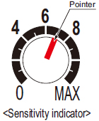
- The pointer shows the present sensitivity level.
|
| Assist function |
|---|
- This product incorporates an "assist function", which helps to easily search the optimum sensitivity position by flashing of the pointer. In order to make "assist function" effective, switch the operation selection switch in the order L-ON (Light ON) → D-ON (Dark ON) → L-ON (Light ON).
Notes:
| 1) | "Assist function" cannot be used when adjusting sensitivity for moving objects. |
|---|---|
| 2) | "Assist function" turns off automatically once the sensitivity adjustment has been completed. |
| 3) | In case "assist function" is not to be used, set the operation selection switch to D-ON (Dark ON) and wait for 2 sec., or more, to make "assist function" ineffective. |
| Step | Sensing method | Operation | Sensitivity indicator |
|
|---|---|---|---|---|
| Reflective type | Thru-beam type | |||
| (1) | Make sure that the operation selection switch is set to L-ON (Light ON). In case "assist function" is to be used, switch the operation selection switch in the order of L-ON (Light ON) → D-ON (Dark ON) → L-ON (Light ON). |
Turn the sensitivity adjuster fully counterclockwise. (Minimum sensitivity) |
 |
|
| (2) |  Beam received |
 Beam received |
In the beam received condition, slowly turn the adjuster clockwise and find the point (A) where the sensor is switched ON. The pointer flashes once at the point (A). (Note 1) |  |
| (3) |  Beam not received |
 Beam not received |
In the beam not received condition, slowly turn the adjuster further clockwise until the sensor goes into the ON state again. Once it is switched on, turn the adjuster counterclockwise a little and find the point (B) where it is switched OFF. The pointer flashes twice at the point (B). (Note 2) (If the sensor does not go into the ON state, MAX is the point (B).) |
 |
| (4) | - | - | Turn the adjuster towards the point (A) from the point (B) slowly. The pointer starts flashing when it approaches the optimum sensitivity point and flashes faster at the optimum sensitivity point for 3 sec. This point is the optimum sensitivity point. (Note 2) | 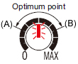 |
| (5) | Select either L-ON (Light ON) or D-ON (Dark ON) according to your application. | |||
Notes:
| 1) | When "assist function" is not used, the pointer does not flash. |
|---|---|
| 2) | When "assist function" is not used, the middle point of (A) and (B) is regarded as the optimum sensitivity point. |
| 3) | In order to protect the mechanism, the sensitivity adjuster idles when over turned, which may result in a backlash of 1 to 2 divisions. |
| 4) | Depending upon the sensing conditions, stable sensing may be possible at a position which is slightly shifted from the optimum sensitivity point. |
| 5) | Do not move or bend the fiber cable after the sensitivity adjustment. Detection may become unstable. |
Others
- Do not use during the initial transient time (0.5 sec. approx.) after the power supply is switched on.
- Take care that the sensor is not directly exposed to fluorescent lamp from a rapid-starter lamp, a high frequency lighting device or sunlight etc. , as it may affect the sensing performance.
- This sensor is suitable for indoor use only.
- Do not use this sensor in places having excessive vapor, dust, etc., or where it may come in contact with corrosive gas.
- Take care that the sensor does not come in contact with water, oil, grease, organic solvents, such as, thinner etc., or strong acid, and alkaline.
- This sensor cannot be used in an environment containing inflammable or explosive gases.
- Never disassemble or modify the sensor.
BY EMAIL
- U.S.A.
- +1-800-344-2112
- Europe
- +49-89-45354-1000
- China
- +86-10-59255988
- Singapore
- +65-6299-9181


Requests to customers (Automation Control Components & Industrial Device) [Excluding specific product]
Requests to customers (Automation Control Components & Industrial Device) [For specific product]
Requests to customers (FA Sensors & Components [Excluding motors])
Requests to customers (Dedicated to industrial motors)
- COMPONENTS & DEVICES
- FA SENSORS & COMPONENTS
- Fiber Sensors
- Photoelectric Sensors / Laser Sensors
- Micro Photoelectric Sensors
- Light Curtains / Safety Components
- Area Sensors
- Inductive Proximity Sensors
- Particular Use Sensors
- Sensor Options
- Wire-Saving Systems
- Programmable Controllers / Interface Terminal
- Human Machine Interface
- Pressure Sensors / Flow Sensors
- Measurement Sensors
- Static Control Devices
- Laser Markers / 2D Code Readers
- Machine Vision System
- Energy Management Solutions
- Timers / Counters / FA Components
- MOTORS
![]()