【Notification of Manufacturer Change for Panasonic Industrial Devices SUNX Products and Panasonic Industrial Devices SUNX Tatsuno Products】
From April 1, 2024, the terms "Panasonic Industrial Devices SUNX Co., Ltd." and "Panasonic Industrial Devices SUNX Tatsuno Co., Ltd."
in this page and in the manuals and other documents to be downloaded will all be replaced with "Panasonic Industry Co., Ltd." and applied accordingly.

 Business
> Industrial Devices
> Automation Controls Top
> FA Sensors & Components
> Sensors
> Fiber Sensors
> Communication Unit for CC-Link SC-GU2-C
> Specifications
Business
> Industrial Devices
> Automation Controls Top
> FA Sensors & Components
> Sensors
> Fiber Sensors
> Communication Unit for CC-Link SC-GU2-C
> Specifications
Communication Unit for CC-Link SC-GU2-C
Specifications
Communication unit for CC-Link
| Designation | Communication unit for CC-Link | ||||
|---|---|---|---|---|---|
| Model No. | SC-GU2-C | ||||
| Applicable sensor amplifier (Note 2) |
Sensor amplifiers (NPN output type) that can connect to non-line connector CN-70 (optional) (FX-500/300/311/410 series, LS-401/403, DPS-401/402, GA-311) |
||||
| Number of connectable units | Max. 16 units (Sensor amplifiers / input units / I/O extension units) per SC-GU2-C (Maximum of 12 units including the FX-500 Series can communicate optically) |
||||
| Supply voltage | 24 V DC +10−15 % Ripple P-P 10 % or less | ||||
| Current consumption | 110 mA or less (excluding connected sensor amplifiers / input units / I/O extension units) | ||||
| Allowable passing current | Wire-saving connector 2 A (Note 3), supply connector 6 A (Note 4) | ||||
| Communication method | CC-Link Ver.1.10 | ||||
| Number of occupied station | Switchable 1 or 4 station | ||||
| Baud rate | 10 Mbps | 5 Mbps | 2.5 Mbps | 625 kbps | 156 kbps |
| Total extension length | 100 m 328.084 ft |
150 m 492.126 ft |
200 m 656.168 ft |
600 m 1968.504 ft |
1,200 m 3937.008 ft |
| Communication cable | Specified cable (twist pair cable with shield) (Note 5) | ||||
| Station No. setting | 1 to 64 (0 and 65 or more: Error) | ||||
| Remote station type | Remote device station | ||||
| Ambient temperature | –10 to +55 ℃ +14 to +131 ℉ (If 4 to 7 units are connected in cascade: –10 to +50 ℃ +14 to +122 ℉, if 8 to 16 units are connected in cascade : –10 to +45 ℃ +14 to +113 ℉) (No dew condensation or icing allowed), Storage: –20 to +70 ℃ –4 to +158 ℉ |
||||
| Ambient humidity | 35 to 85 % RH, Storage: 35 to 85 % RH | ||||
| Material | Enclosure: Heat-resistant ABS, Connector cap: Silicone rubber | ||||
| Weight | Net weight: 60 g approx., Gross weight: 100 g approx. | ||||
| Accessory | Connector cap: 2 pcs. | ||||
Notes:
1) Where measurement conditions have not been specified precisely, the conditions used were an ambient temperature of +23 ℃ +73.4℉.
2) Only the below models respond to data communication.
FX-501/502, FX-301/305, LS-403, DPS-401/402
3) Be sure to check that total current consumption of sensor amplifiers connected in cascade does not exceed allowable passing current.
4) In case of supplying power to other devices, be sure to set the current less than allowable passing current.
5) Use the CC-Link-specified cable.
1-channel connector input extension unit
| Designation | 1-channel connector input extension unit |
|---|---|
| Analog communication unit | |
| Model No. | SC-T1JA |
| Supply voltage | 12 to 24 V DC ±10 % Ripple P-P 10 % or less (By power supplied from the SC-GU2-C.) |
| Current consumption (Note 2) | Max. 25 mA or less (when all indicators light up) |
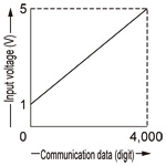
| Analog voltage input | Input voltage range: 1 to 5 V DC Input impedance: 200 kΩ approx. |
| Communication data (Note 3) |
Analog <--> Communication data • Communication data: 0 to 4,000 digits (in the range of 1 to 5 V) • Zero point: Within 0 digit ±0.5 % F.S. • Span: Within 4,000 digits ±0.5 % F.S. • Linearity: Within ±0.5 % F.S. |
| Input | Connectable device: Output type of NPN open-collector transistor Supply current for input device: 100 mA or less Input impedance: 17 kΩ approx. Operating voltage: 17 V or more at ON voltage (between input and +V at 24 V) 4 V or less at OFF voltage (between input and +V at 24 V) |
| Output | NPN open-collector transistor • Max. sink current: 50 mA • Applied voltage: 30 V DC or less • Residual voltage: 1.5 V or less (at 50 mA sink current) |
| Power indicator | Green LED (lights up when the power is ON) |
| Input indicator | Green LED (lights up when NPN input is ON) |
| Ambient temperature |
–10 to +55 ℃ +14 to +131 ℉ (If 4 to 7 units are connected in cascade: –10 to +50 ℃ +14 to +122 ℉, if 8 to 16 units are connected in cascade : –10 to +45 ℃ +14 to +113℉) (No dew condensation or icing allowed), Storage: –10 to +70 ℃ +14 to +158 ℉ |
| Ambient humidity | 35 to 85 % RH, Storage: 35 to 85 % |
| Temperature characteristics | Within ±1 % F.S. (at +25 ℃ +77 ℉ reference) |
| Material | Enclosure: Heat-resistant ABS |
| Weight | Net weight: 20 g approx., Gross weight: 40 g approx. |
| Accessory | Connector (e-CON): 1 pc. |
Notes:
1) Where measurement conditions have not been specified precisely, the conditions used were an ambient temperature of +23 ℃ +73.4 ℉.
2) The current consumption and input current of output device connected are not included.
3) The relationship between communication data and input voltage is as described in the below figure.
|
End unit
| Designation | End unit | |
|---|---|---|
| Model No. | SC-GU2-EU | |
| Supply voltage | 12 to 24 V DC +10−15 % Ripple P-P 10 % or less (By power supplied from the SC-GU2-C) | |
| Current consumption | 10 mA or less | |
| Signal channel No. | - (Not occupy the signal channel No.) | |
| Power indicator | Green LED (lights up when the power is ON) | |
| Cable | Type | 0.38 mm2 single shielded cable [Heat resistant PVC (Black)] |
| Sheath outer diameter | φ1.46 mm φ0.057 in | |
| Length | 30 to 180 mm 1.181 to 7.087 in adjustable by cable length adjust button | |
| Tensile strength | Main body side: 20 N (Note 2) | |
| Material | Enclosure: Heat-resistant ABS | |
| Weight | Net weight: 20 g approx., Gross weight: 40 g approx. | |
Notes:
1) Where measurement conditions have not been specified precisely, the conditions used were an ambient temperature of +23 ℃ +73.4 ℉.
2) For length adjustment of cable with communication connector, pull out the cable slowly. To remove the cable with communication connector from SC-GU2-C, hold the connector and remove it.
Connector input extension units / connector I/O extension units
| Designation | 1-channel connector input extension unit | 8-channel connector input extension unit | 8-channel connector I/O mixed extension unit |
|---|---|---|---|
| Model No. | SC-T1J | SC-T8J | SC-TP8J |
| Supply voltage | 12 to 24 V DC ±10 % (By power supplied from the SC-GU2-C) | 5 to 24 V DC ±10 % (Note 2) | |
| Current consumption (Note 3) |
20 mA or less (when all indicators light up) | 60 mA or less (when all indicators light up) | 7 mA or less |
| Signal channel No. | 1 input | 8 inputs (Note 4) | 8 inputs / outputs (Note 5) |
| Connectable device | NPN open-collector, or DC 2-wire output type sensor, or switch etc. | NPN open-collector output sensor or switch etc. (Note 6) | commercially available I/O device including DC 2-wire type sensor |
| Supply current for units (Note 7) |
100 mA or less | 800 mA or less (At a total of 8 channels) | |
| Power indicator | Green LED (Lights up when the power is ON) | ||
| Input indicator | Green LED [SC-T1J: 1 No., SC-T8J: 8 Nos.] (Lights up when each channel input is ON) | - | |
| Ambient temperature | –10 to +45 ℃ +14 to +113 ℉ (No dew condensation or icing allowed), Storage: –20 to +70 ℃ –4 to +158 ℉ |
||
| Ambient humidity | 35 to 85 % RH, Storage: 35 to 85 % RH | ||
| Material | Enclosure: Heat-resistant ABS | ||
| Net weight | 10 g approx. | 40 g approx. | |
| Accessories | SL-CP1 (Snap male connector): 1 pc. | Index seal : 1 pc. | |
Notes:
1) Where measurement conditions have not been specified precisely, the conditions used were an ambient temperature of +20 ℃ +68 ℉.
2) It depends on the power supply from SC-MIL.
3) The current consumption and input current of the input unit connected are not included.
4) The signal for 8 channels is occupied regardless of number of input units connected.
5) The signal for 8 channels is occupied regardless of number of I/O units connected.
6) DC 2-wire type sensor and switch etc. cannot be connected (SC-T8J only).
7) Set the maximum current passing through input / output line to 50 mA or less.
Plug-in Sensor units (MIL connectors)
| Designation | Separate unit | Main unit |
|---|---|---|
| Model No. | SC-MIL-S | SC-MIL |
| Supply voltage | By power supplied from the SC-GU2-C | 12 to 24 V DC ±10 % (Note 2) By power supplied from the SC-GU2-C |
| Allowable through current (Note 3) |
1 A or less (Same as maximum permissible current consumption of all units connected to SC-MIL-S.) |
2 A or less (Same as maximum permissible current consumption of all units connected to SC-MIL.) |
| Signal channel No. | Connectable up to 16 channels (The signal from up to 16th point (counting from unit adjacent to SC-MIL) of all units connected to SC-MIL is transferred. However, the signal thereafter is not transferred. Note that SC-MIL and SC-MIL-S do not occupy any signal point.) |
|
| Max. distance between units | 10 m 32.808 ft or less (the distance between SC-MIL and PLC and that between SC-MIL and SC-MIL-S put together) | |
| Ambient temperature | –10 to +45 ℃ +14 to +113 ℉ (No dew condensation or icing allowed), Storage: –20 to +70 ℃ –4 to +158 ℉ |
|
| Ambient humidity | 35 to 85 % RH, Storage: 35 to 85 % RH | |
| Material | Enclosure: Heat-resistant ABS | |
| Weight | Net weight: 20 g approx. | Net weight: 25 g approx. |
| Accessory | Connector protection seal: 1 pc. | |
Notes:
1) Where measurement conditions have not been specified precisely, the conditions used were an ambient temperature of +20 ℃ +68 ℉.
2) The plug-in sensor main unit SC-MIL incorporates a cable lead-out connector in addition to the MIL connector, which allows to receive the supply
voltage from the separate power supply.
3) When either the power supply device’s allowable amount of current or the connecting cable’s allowable amount of current is smaller than the allowable
current passage value, match it with the smallest specification.
BY EMAIL
- U.S.A.
- +1-800-344-2112
- Europe
- +49-89-45354-1000
- China
- +86-10-59255988
- Singapore
- +65-6299-9181


Requests to customers (Automation Control Components & Industrial Device) [Excluding specific product]
Requests to customers (Automation Control Components & Industrial Device) [For specific product]
Requests to customers (FA Sensors & Components [Excluding motors])
Requests to customers (Dedicated to industrial motors)
- COMPONENTS & DEVICES
- FA SENSORS & COMPONENTS
- Fiber Sensors
- Photoelectric Sensors / Laser Sensors
- Micro Photoelectric Sensors
- Light Curtains / Safety Components
- Area Sensors
- Inductive Proximity Sensors
- Particular Use Sensors
- Sensor Options
- Wire-Saving Systems
- Programmable Controllers / Interface Terminal
- Human Machine Interface
- Pressure Sensors / Flow Sensors
- Measurement Sensors
- Static Control Devices
- Laser Markers / 2D Code Readers
- Machine Vision System
- Energy Management Solutions
- Timers / Counters / FA Components
- MOTORS
![]()