【Notification of Manufacturer Change for Panasonic Industrial Devices SUNX Products and Panasonic Industrial Devices SUNX Tatsuno Products】
From April 1, 2024, the terms "Panasonic Industrial Devices SUNX Co., Ltd." and "Panasonic Industrial Devices SUNX Tatsuno Co., Ltd."
in this page and in the manuals and other documents to be downloaded will all be replaced with "Panasonic Industry Co., Ltd." and applied accordingly.
Ultra-compact Photoelectric Sensor EX-20 Ver.2
Cautions For Use
- Never use this product as a sensing device for personnel protection.
- In case of using sensing devices for personnel protection, use products which meet laws and standards, such as OSHA, ANSI or IEC etc., for personnel protection applicable in each region or country.
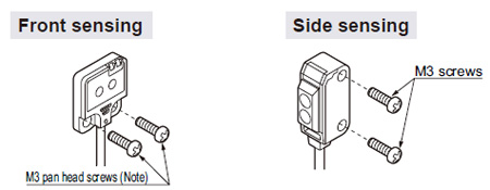
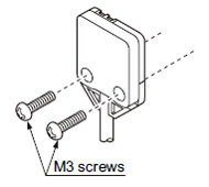
Mounting
- Mount using M3 screws. The tightening torque should be 0.5 N·m or less.
| Note: |
When mounting the front sensing type sensor, use M3 pan head screws without washers, etc. |
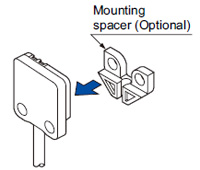
- When mounting the front sensing type from the backside, fit the mounting spacer (MS-EX20-FS) and fix with screws.
| 1 |
Fit the mounting spacer on the sensor. |
|
|---|
 |
|
|
| 2 |
Align the mounting holes of the mounting spacer and the sensor and mount with M3 screws. The tightening torque should be 0.5 N·m or less. |
|
|---|
 |
|
|
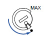
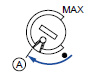
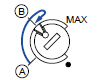
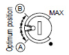
Sensitivity adjustment (side sensing type only)
Operation mode switch (EX-23□ only)
Switch
position |
Description |
 |
Light-ON mode is obtained when the operation mode switch (located on the receiver) is turned fully clockwise (L side). |
 |
Dark-ON mode is obtained when the operation mode switch (located on the receiver) is turned fully counterclockwise (D side). |
| Note: |
Operation mode switch should be turned fully till it stops. |
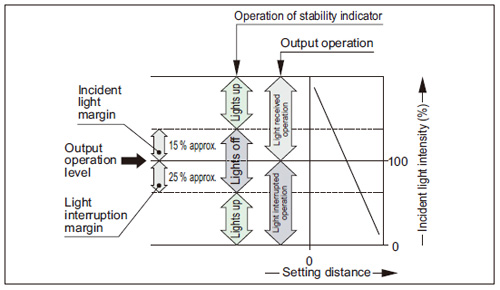
Stability indicator
- The stability indicator (green) lights up when the incident light intensity has sufficient margin with respect to the operation level.
If the incident light intensity level is such that the stability indicator lights up, stable sensing can be done without the light received operation and the light interrupted operation being affected by a change in ambient temperature or supply voltage.
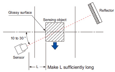
Glossy object sensing (EX-29□)
- Please take care of the following points when detecting materials having a gloss.
Wiring
- Excess bending of the cable or stress applied to the cable may disconnect the internal lead wire.
Others
- Do not use during the initial transient time (50 ms) after the power supply is switched on.
- If sensors are mounted close together and the ambient temperature is near the maximum rated value, provide for enough heat radiation / ventilation.
- If a reflective object is present in the background, the sensing of EX-28□ may be affected. When setting the sensor, make sure to confirm that the reflective object has no effect. In case the reflective object affects the sensing, take measures such as removing the reflective object or coloring it in black, etc.
Return to top
Return to top

 Business
> Industrial Devices
> Automation Controls Top
> FA Sensors & Components
> Sensors
> Photoelectric Sensors / Laser Sensors
> Ultra-compact Photoelectric Sensor EX-20 Ver.2
> Cautions For Use
Business
> Industrial Devices
> Automation Controls Top
> FA Sensors & Components
> Sensors
> Photoelectric Sensors / Laser Sensors
> Ultra-compact Photoelectric Sensor EX-20 Ver.2
> Cautions For Use