【Notification of Manufacturer Change for Panasonic Industrial Devices SUNX Products and Panasonic Industrial Devices SUNX Tatsuno Products】
From April 1, 2024, the terms "Panasonic Industrial Devices SUNX Co., Ltd." and "Panasonic Industrial Devices SUNX Tatsuno Co., Ltd."
in this page and in the manuals and other documents to be downloaded will all be replaced with "Panasonic Industry Co., Ltd." and applied accordingly.
Leak Detection Sensor EX-F70/EX-F60
Partly Order Discontinued
General purpose
 |
September 29, 2023 |
|
|
Cautions For Use
- Never use this product as a sensing device for personnel protection.
- In case of using sensing devices for personnel protection, use products which meet laws and standards, such as OSHA, ANSI or IEC etc., for personnel protection applicable in each region or country.
Mounting
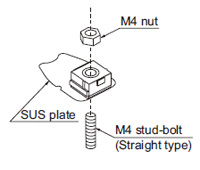
EX-F71(-PN)
- Insert the M4 stud-bolt (length 10 mm 0.394 in or more) welded on the user’s facilities into the mounting hole of the SUS mounting bracket and screw with an M4 nut (please arrange separately). The tightening torque should be 0.98 N·m or less.
|
|
EX-F72(-PN)
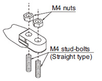
<In case of using the two-point-fixing PVC mounting bracket>
- Insert M4 stud-bolts (length 10 mm 0.394 in or more) welded on the user’s facilities into the mounting holes of the two-point-fixing mounting bracket and screw with M4 nuts (please arrange separately). The tightening torque should be 0.49 N·m or less.
|
|
<In case of using the PVC mounting bracket for adhesive fixing>
- Use adhesive to stick fast the mounting bracket on the mounting surface. Please note that if the adhesive sticks out from the bottom surface of the mounting bracket or is 0.5 mm 0.020 in, or more thick, the sensor body cannot be fitted to the mounting bracket.
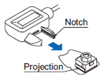
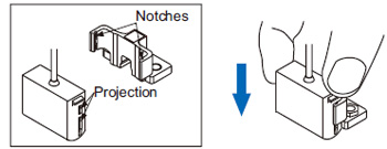
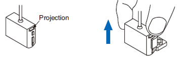
How to fit the sensor body to the exclusive mounting bracket
- Match the notch in the sensor body with the projection of the exclusive mounting bracket and slide till a click is felt.
- When mounting, make sure to use the brackets included with the unit in order to eliminate human error (such as forgetting to install). If the included brackets are not used, stable sensing is rendered impossible. Also, because sensitivity settings differ between the EX-F71(-PN) and the EX-F72(-PN), their brackets cannot be interchanged.
|
|
Mounting
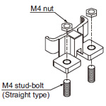
EX-F61(-PN)
- Insert the M4 stud-bolt (length 10 mm 0.394 in or more) welded on the user’s facilities into the mounting hole of the PFA mounting bracket and screw with an M4 nut (please arrange separately). The tightening torque should be 0.98 N·m or less.
|
|
EX-F62(-PN)
- Please note that if the excess adhesive from the bottom surface of the exclusive mounting bracket is remained, the sensing capability may be affected. Use adhesive for vinyl chloride (PVC).
How to fit the sensor body to the exclusive mounting bracket
- Align the projections in the sensor body with the notches of the exclusive mounting bracket and slide till a click is felt.
|
 |
|
How to remove the sensor body from the exclusive mounting bracket
- Pinch the projections of the sensor body and pull the body upwards. Never pull the cable, since it may cause a cable break.
|
 |
|
Mounting
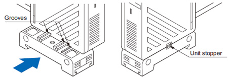
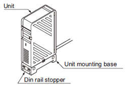
- When mounting the unit, be sure to use the unit mounting base (MS-SL-2) (accessory).
- When installing the unit mounting base to the unit, insert the base aligned with the grooves of the unit and move until the unit stopper is locked.
- Two installation positions are available for the unit mounting base so that the unit direction can be changed. Install the base at one of them.
| Mounting position 1 |
|---|
 |
|
|
| Mounting position 2 |
|---|
 |
|
|
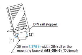
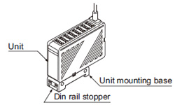
<In case of using a DIN rail or the mounting bracket (MS-DIN-3)
(optional)>
| [1] |
Fit the rear part of the unit mounting base on a 35 mm 1.378 in width DIN rail or the mounting bracket (MS-DIN-3) (optional). |
| [2] |
Press down the front part of the unit mounting base on the 35 mm 1.378 in width DIN rail or the mounting bracket (MS-DIN-3) (optional) and fit the front part of the base. |
|
|
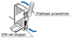
| * |
For removal, insert a flathead screwdriver into the DIN rail stopper and pull towards yourself. |
|
|
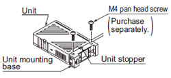
<In case of using screws>
- Mount using M4 pan head screws with a tightening torque of 0.8 N·m or less. However, in case of side mounting, make sure to mount the unit such that the unit stopper faces front.
|
|
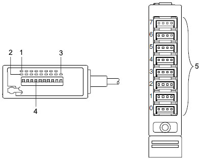
Part description
| |
Designation |
Function |
| 1 |
Normal indicator
(Green LED x 8) |
Lights up when sensors are connected to each channel and the connection setting switch is set to ON. |
| 2 |
Error indicator
(Red LED x 8) |
Lights up when leak is detected by any sensor connected or any sensor is mounted improperly. |
| 3 |
Output indicator
(Orange LED) |
Lights up when the output relay is ON (Normal). |
| 4 |
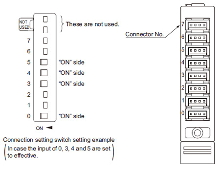
Connection setting switch |
Set the switch to ON when the leak detection sensor is connected, set to OFF when the leak detection sensor is not connected. |
| 5 |
Connector |
Connect the leak detection sensors. |
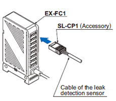
Connection
| • Make sure to connect or disconnect the snap male
connector (SL-CP1) in the power supply off condition. |
| • Take care that wrong wiring will damage the product. |
| • The terminal No. 4 of the snap male connector (SL-CP1) is not used. Take care not to connect to the terminal No. 4 by mistake. Further, if there are unused wires, please insulate them. |
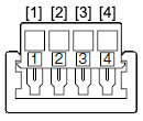
| |
Content |
| [1] |
+V |
| [2] |
0V |
| [3] |
IN |
| [4] |
No connected |
|
| • For details of the hook-up method of the snap male connector (SL-CP1), refer to the Instruction Manual enclosed with SL-CP1. |
Connection method
- By holding the SL-CP1 with the cable connected, insert it into the connector of the EX-FC1 reliably till it stops.
Disconnection method
- By holding SL-CP1, pull it from the EX-FC1 horizontally.
| Note: |
Do not pull out by holding the cable, as this can result in cable disconnection. |
|
|
EX-FC1
Connection setting switch
| • The connection setting should be carried out in the power supply off condition after removing any electrostatic charge which may be present on your body. |
Operation matrix for each indicator
| Operation |
Connection state of the leak detection sensor |
State of the connection setting switch |
Leak detected condition |
Normal indicator
(Green) |
Error indicator
(Red) |
Output indicator
(Orange) |
| Normal |
Connected |
ON |
Not leaked |
Lights up |
Turns off |
Lights up |
| Leaked |
Turns off |
Lights up |
Turns off |
| Unconnected |
OFF |
- |
Turns off |
Turns off |
Lights up |
| Error |
Connected |
OFF |
Not leaked |
Lights up |
Lights up |
Turns off |
| Unconnected |
ON |
- |
Turns off |
Lights up |
Turns off |
- For the channel that the unit sensor is connected to and the connection setting switch is set to “ON” side, the error indicator (red) lights up for a moment when the power is turned on. This is not a malfunction for the unit because it is caused by characteristic of the sensor.
- Make sure to set the connection setting switch with the connector No. to which the leak detection sensor is connected, to “ON” side.
- In case both the normal indicator (green) and the error indicator (red) light up, the connection setting switch with the connector No. to which the leak detection sensor is connected, is not set to “ON” side. Set the connection setting switch with the connector No. to which the leak detection sensor is connected, to “ON” side.
- In case the error indicator (red) lights up, the leak detection sensor detects leak or the connection setting switch is set to “ON” side without connecting the leak detection sensor. If the connection setting switch is set to “ON” side without connecting the leak detection sensor, set the connection setting switch to “OFF” side.
- If the leak detection sensor detects leak or the connection setting switch is set to “OFF” side in the state that the leak detection sensor is improperly mounted to the mounting bracket, the sensor judges as the output is ON. Be careful when setting.
All models
Wiring
- Make sure that the power supply is off while wiring.
- Verify that the supply voltage variation is within the rating. Take care that if a voltage exceeding the rated range or an AC power supply is directly applied, the sensor may get damaged or burnt.
- If power is supplied from a commercial switching regulator, ensure that the frame ground (F.G.) terminal of the power supply is connected to an actual ground.
- In case noise generating equipment (switching regulator, inverter motor,etc.) is used in the vicinity of this product, connect the frame ground (F.G.) terminal of the equipment to an actual ground.
- Do not run the wires together with high-voltage lines or power lines or put them in the same raceway. This can cause malfunction due to induction.
- Make sure to use an isolation transformer for the DC power supply. If an auto-transformer (single winding transformer) is used, this product or the power supply may get damaged.
- In case a surge is generated in the used power supply, connect a surge absorber to the supply and absorb the surge.
- Cable extension is possible up to total 50 m 164.05 ft with 0.3 mm2, or more, cable (less than 10 m 32.81 ft for EX-FC1). However, in order to reduce noise, make the wiring as short as possible.
- Make sure that stress by forcible bend or pulling is not applied directly to the sensor cable joint.
- EX-FC1 output dose not incorporate a short-circuit protection circuit. Do not connect it directly to a power supply or a capacitive load.
Others
| • Avoid using the product in an explosive atmosphere because this product does not have an explosive-proof protective construction. |
| • When liquid remains on the sensing surface after leak detection, wipe all liquid from the sensing surface. To avoid scratching the sensing surface and the enclosed mounting bracket, use a soft cloth. |
- In case air bubbles are drawn into the sensing part, take care that it may take some time for sensing to stabilize, or sensing may even become unstable. Check the usage conditions thoroughly before use.
- Do not use during the initial transient time (leak detection sensor: 50 ms approx., EX-FC1: 0.5 sec. approx.) after the power supply is switched on.
- Since this sensor employs non-modulated infrared LED, take sufficient care against extraneous light. Do not expose the sensing part directly to the extraneous light.
- Avoid dust, dirt, and steam. Further, do not use this product in an environment containing organic solvents.
- Take care that EX-7□(-PN) and EX-FC1 does not come in contact with oil, grease or organic solvents, such as, thinner, etc.
- In case this sensor is used where electrostatic charge is present, use a metal leak pan, which should be connected to an actual ground.
- These sensors are only for indoor use.
Return to top
Return to top

 Business
> Industrial Devices
> Automation Controls Top
> FA Sensors & Components
> Sensors
> Photoelectric Sensors / Laser Sensors
> Leak Detection Sensor EX-F70/EX-F60
> Cautions For Use
Business
> Industrial Devices
> Automation Controls Top
> FA Sensors & Components
> Sensors
> Photoelectric Sensors / Laser Sensors
> Leak Detection Sensor EX-F70/EX-F60
> Cautions For Use