【Notification of Manufacturer Change for Panasonic Industrial Devices SUNX Products and Panasonic Industrial Devices SUNX Tatsuno Products】
From April 1, 2024, the terms "Panasonic Industrial Devices SUNX Co., Ltd." and "Panasonic Industrial Devices SUNX Tatsuno Co., Ltd."
in this page and in the manuals and other documents to be downloaded will all be replaced with "Panasonic Industry Co., Ltd." and applied accordingly.

 Business
> Industrial Devices
> Automation Controls Top
> FA Sensors & Components
> Sensors
> Photoelectric Sensors / Laser Sensors
> LED Type Wafer Alignment Sensor Controller HD-T1
> Cautions For Use
Business
> Industrial Devices
> Automation Controls Top
> FA Sensors & Components
> Sensors
> Photoelectric Sensors / Laser Sensors
> LED Type Wafer Alignment Sensor Controller HD-T1
> Cautions For Use
LED Type Wafer Alignment Sensor Controller HD-T1
Cautions For Use
- Never use this product as a sensing device for personnel protection.
- In case of using sensing devices for personnel protection, use products which meet laws and standards, such as OSHA, ANSI or IEC etc., for personnel protection applicable in each region or country.
| ・ | Make sure to use the sensor head and the controller together as a set. |
|---|
Mounting
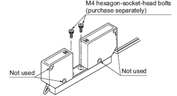
Sensor head
- Mount the sensor head using 2 pcs. M4 hexagon-sockethead bolts (purchase separately) with a tightening torque of 0.5 N·m or less.
- Do not remove the screws fixing the emitter / receiver and the mounting base. If removed, the output value will change.
- Do not fix with the screws, using the mounting hole on the side of emitter / receiver.
|
Controller
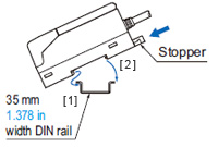
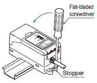
<In case of using DIN rail>
| [1] | Fit the front part of the mounting section of the unit on the 35 mm 1.378 in width DIN rail, pressing the stopper towards the arrow (the stopper is locked) shown in the right figure. |
|---|---|
| [2] | Press down the rear part of the mounting section of the unit on the 35 mm 1.378 in width DIN rail to fit it. |
|
|
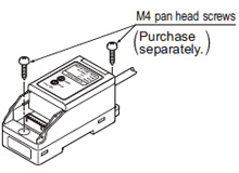
<In case of using screws>
- Mount using M4 pan head screws with a tightening torque of 1.2 N·m or less.
|
Wiring
- Analog output of controller does not incorporate a shortcircuit protection circuit. Do not connect it directly to a power supply or a capacity load.
- Care should be taken that static electricity is not applied to the connector during wiring. It may damage the product.
- Take care that wrong wiring will damage the product.
- Cable extension is possible up to total 3 m 9.843 ft with 0.3 mm2, or more, cable. Note that the cable length of the sensor head cannot be changed.
- Do not apply stress such as forced bending and pulling to the cable joint.
- Make sure to use an isolation transformer for the DC power supply. If an autotransformer (single winding transformer) is used, this product or the power supply may get damaged.
- In case a surge is generated in the used power supply, connect a surge absorber to the supply and absorb the surge.
Others
- Do not use during the initial transient time (0.5 sec. approx.) after the power supply is switched on.
- This product outputs according to the amount of LED light received. Optical power varies between the center and the periphery of sensing range, and note that dimensional accuracy cannot be assured.
- Do not allow any water, oil, fingerprints, etc., which may refract light, or dust, dirt, etc., which may block light, to stick to the emitting / receiving surfaces of the sensor head. In case they are present, wipe them with a clean, dust-free soft cloth or lens paper.
- If the sensing object is specular or transparent object, note that accurate measurement may not be possible.
BY EMAIL
- U.S.A.
- +1-800-344-2112
- Europe
- +49-89-45354-1000
- China
- +86-10-59255988
- Singapore
- +65-6299-9181


Requests to customers (Automation Control Components & Industrial Device) [Excluding specific product]
Requests to customers (Automation Control Components & Industrial Device) [For specific product]
Requests to customers (FA Sensors & Components [Excluding motors])
Requests to customers (Dedicated to industrial motors)
- COMPONENTS & DEVICES
- FA SENSORS & COMPONENTS
- Fiber Sensors
- Photoelectric Sensors / Laser Sensors
- Micro Photoelectric Sensors
- Light Curtains / Safety Components
- Area Sensors
- Inductive Proximity Sensors
- Particular Use Sensors
- Sensor Options
- Wire-Saving Systems
- Programmable Controllers / Interface Terminal
- Human Machine Interface
- Pressure Sensors / Flow Sensors
- Measurement Sensors
- Static Control Devices
- Laser Markers / 2D Code Readers
- Machine Vision System
- Energy Management Solutions
- Timers / Counters / FA Components
- MOTORS
![]()