【Notification of Manufacturer Change for Panasonic Industrial Devices SUNX Products and Panasonic Industrial Devices SUNX Tatsuno Products】
From April 1, 2024, the terms "Panasonic Industrial Devices SUNX Co., Ltd." and "Panasonic Industrial Devices SUNX Tatsuno Co., Ltd."
in this page and in the manuals and other documents to be downloaded will all be replaced with "Panasonic Industry Co., Ltd." and applied accordingly.

 Business
> Industrial Devices
> Automation Controls Top
> FA Sensors & Components
> Sensors
> Photoelectric Sensors / Laser Sensors
> Amplifier-separated Type Digital Laser Sensor LS-500
> I/O Circuit and Wiring diagrams
Business
> Industrial Devices
> Automation Controls Top
> FA Sensors & Components
> Sensors
> Photoelectric Sensors / Laser Sensors
> Amplifier-separated Type Digital Laser Sensor LS-500
> I/O Circuit and Wiring diagrams
Amplifier-separated Type Digital Laser Sensor LS-500
|
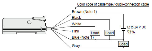
I/O Circuit and Wiring diagrams
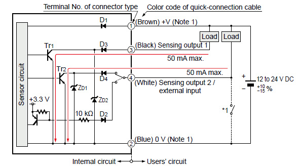
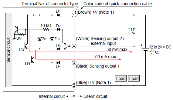
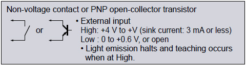
I/O circuit diagram NPN output type
|
|
|
|
Terminal layout of connector type
|
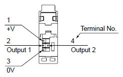
* Connector for amplifier (CN-EP4) pin position
|
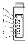
| Terminal No. | Connection cable |
|---|---|
| 1 | Purple |
| 2 | White |
| 3 | Shield |
| 4 | Shield |
| 5 | Black |
| 6 | Pink |
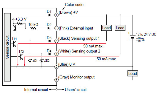
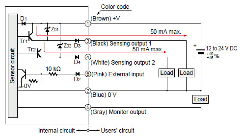
I/O circuit diagram PNP output type
|
|
|
|
Terminal layout of connector type
|
* Connector for amplifier (CN-EP4) pin position
|
| Terminal No. | Connection cable |
|---|---|
| 1 | Purple |
| 2 | White |
| 3 | Shield |
| 4 | Shield |
| 5 | Black |
| 6 | Pink |
BY EMAIL
- U.S.A.
- +1-800-344-2112
- Europe
- +49-89-45354-1000
- China
- +86-10-59255988
- Singapore
- +65-6299-9181


Requests to customers (Automation Control Components & Industrial Device) [Excluding specific product]
Requests to customers (Automation Control Components & Industrial Device) [For specific product]
Requests to customers (FA Sensors & Components [Excluding motors])
Requests to customers (Dedicated to industrial motors)
- COMPONENTS & DEVICES
- FA SENSORS & COMPONENTS
- Fiber Sensors
- Photoelectric Sensors / Laser Sensors
- Micro Photoelectric Sensors
- Light Curtains / Safety Components
- Area Sensors
- Inductive Proximity Sensors
- Particular Use Sensors
- Sensor Options
- Wire-Saving Systems
- Programmable Controllers / Interface Terminal
- Human Machine Interface
- Pressure Sensors / Flow Sensors
- Measurement Sensors
- Static Control Devices
- Laser Markers / 2D Code Readers
- Machine Vision System
- Energy Management Solutions
- Timers / Counters / FA Components
- MOTORS
![]()