【Notification of Manufacturer Change for Panasonic Industrial Devices SUNX Products and Panasonic Industrial Devices SUNX Tatsuno Products】
From April 1, 2024, the terms "Panasonic Industrial Devices SUNX Co., Ltd." and "Panasonic Industrial Devices SUNX Tatsuno Co., Ltd."
in this page and in the manuals and other documents to be downloaded will all be replaced with "Panasonic Industry Co., Ltd." and applied accordingly.
Long Range & Wide Area Photoelectric Sensor PX-2
Cautions For Use
All models
- Never use this product as a sensing device for personnel protection.
- In case of using sensing devices for personnel protection, use products which meet laws and standards, such as OSHA, ANSI or IEC etc., for personnel protection applicable in each region or country.
Hazard Indications

- Installation of a touch bumper
You are requested to always install a touch bumper when this product is used on an automatic guided vehicle (AGV).

This sensor conforms to the EMC Directive (CE Marking) and EMC Regulations (UKCA Marking). However, it is not certified by a competent body in accordance with other country safety standards. Since each country has its regulations, please follow the local and national regulations of the country where this sensor is used.
This sensor is meant for proximity detection and does not possess control functions for safety maintenance. If fail-safe measures are required, consider their incorporation in the total system. Further, do not connect the sensor output directly to a stopping mechanism (brake).
- Periodical maintenance check
The person in charge must periodically confirm the performance of the product and maintain a record of such checks. In addition, whenever the operating environment of the product is changed due to system modification, etc., performance check must be done.
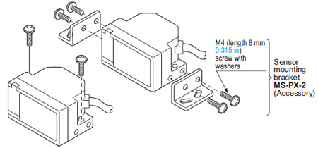
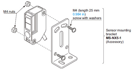
Mounting
| ・ |
The tightening torque for the main sensor should be 1.2 N·m or less. |
| ・ |
The tightening torque for PX-SB1 (auxiliary sensor) should be 0.8 N·m or less. |
|
 |
|
| ・ |
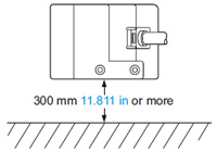
Mount the sensor, horizontally, at least 300 mm 11.811 in above the floor, to avoid reflection from the floor. |
|
 |
|
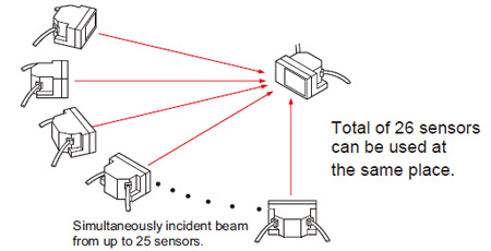
Automatic interference prevention function
| ・ |
In case several sensors are used at the same place, take care that the number of sensors from which beams may be simultaneously incident is 25 sensors or less. |
Sleep function
- When the sleep input is made Low, the sensor goes into the sleep state and the operation can be stopped.
| Notes: 1) |
Response time of the sleep input is 50ms. |
| 2) |
Reactivation from the sleep state to the operation state takes 0.7 sec. approx. Operation during this transient state should be avoided. |
| 3) |
When the sleep function is not used, keep the sleep input wire open or insulated and prevent contact with other wires. |
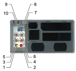
Part description
| Sign |
Item |
Description |
| 1 |
Operation indicator |
OUT 2 area
(Yellow LED) |
Lights up when the beam is received in the OUT 2 area. |
| 2 |
OUT 1 area
(Red LED) |
Lights up when the beam is received in the OUT 1 area. |
| 3 |
Sensitivity adjuster |
OUT 2 area |
Sensing area sensitivity adjuster.
 |
| 4 |
OUT 1 area |
| 5 |
Adjacent right OUT 1 area |
| 6 |
Adjacent left OUT 1 area |
| 7 |
Sensing area selection switch (Note 1) |
Left area |
Selection of main sensor sensing areas. (OUT 1,OUT 2 )
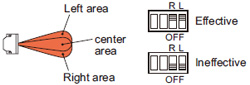 |
| 8 |
Right area |
| 9 |
Output operation mode selection switch |
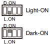 Select the operation mode for OUT 1 and OUT 2 with the operation mode selection switch. Select the operation mode for OUT 1 and OUT 2 with the operation mode selection switch. |
| 10 |
External control function selection switch (Note 2) |
Select whether to perform selection of sensing area with the dipswitch or by external input. |
| Notes: 1) |
Not incorporated in PX-26. |
| 2) |
Incorporated in PX-24ES and PX-23ES. |
Others
- Do not use during the initial transient time (0.7 sec.) after the power supply is switched on.
- Take care that an initial rush current (1.5 A approx. at 10 V DC and 5 A approx. at 31 V DC) will flow when the power supply is switched on.
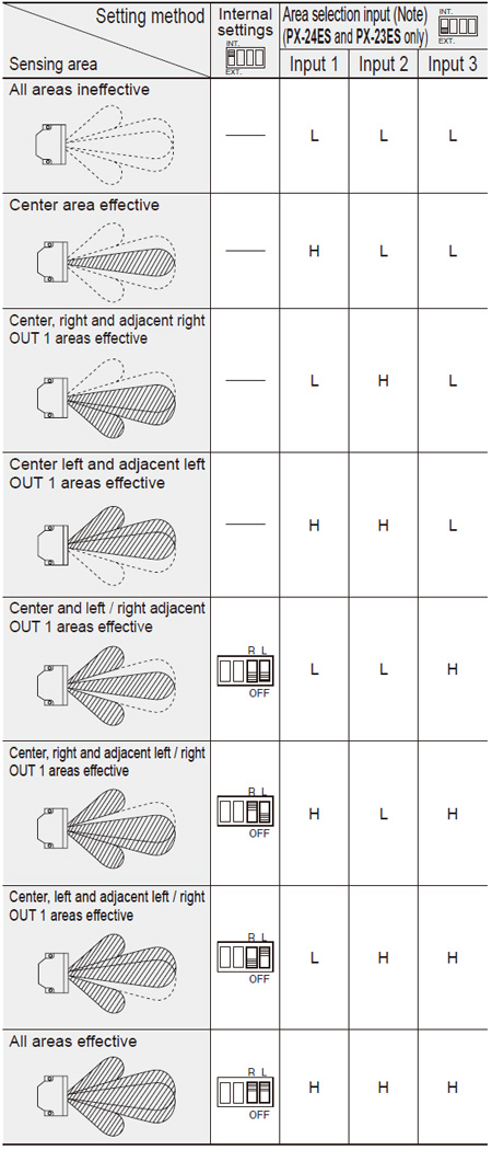
PX-22 PX-21 PX-24 PX-24ES PX-23ES
Selection of sensing area
L: Low (0 to 1V), H: High (4.5 to 31V, or open)
Note: Response time of area the selection input is 80 ms.
PX-24 PX-24ES PX-23ES PX-26
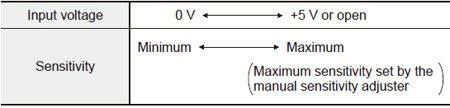
External sensitivity adjustment function
- The sensitivity can be adjusted, within the range set by the manual sensitivity adjuster, by an analog voltage (0 to +5 V) applied to the external sensitivity adjustment input. The sensitivity varies with the magnitude of the applied voltage.
| Notes: 1) |
The sensitivity of the auxiliary sensor is not changed. |
| 2) |
Sensitivity adjustment beyond the range set by the manual sensitivity adjuster is not possible. |
| 3) |
This wire should be insulated if it is not used. |
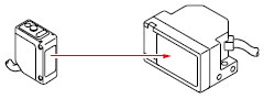
Extraneous light monitor function
(Not incorporated in PX-22 and PX-21)
- If the sensor receives modulated light other than its own (including auxiliary sensor’s) light, the extraneous light monitor output turns ON. The operation of the extraneous light monitor output has absolutely no affect on sensing. It is useful for recognizing presence of other sensors near this sensor in case of intersecting AGV paths, etc.
|
|
| Note: |
The extraneous light monitor output is not incorporated with a short-circuit protection circuit. Do not connect it directly to a power supply or a capacitive load. |
|
PX-SB1
| • This sensor must always be used with the applicable main sensor. This sensor does not work as a standalone unit. (It cannot be used with PX-22 or PX-21.) |
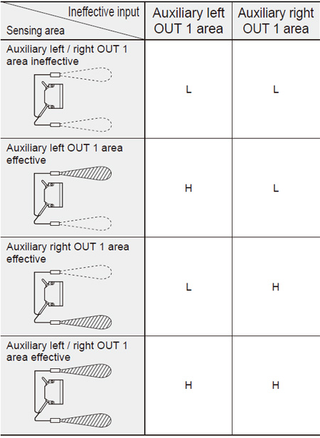
Selection of auxiliary area
- Aux area can be selected by aux area ineffective input of the main sensor.
L: Low (0 to 1 V), H: High (4.5 to 31 V or open)
Note: Aux area disable input has nothing to do with the external control function selection switch of the main sensor.
Sensitivity setting
- Sensitivity adjustment of PX-SB1 is performed with the emitter volume. If sensitivity cannot be set to close range even after adjusting the emitter volume, then an aux sensor might be receiving the light from the main sensor. If that is the case, adjust sensitivity with the emitter volume and the receiver volume. For details, see the instruction manual that comes with the product.
Connection with the main sensor
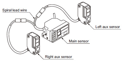
- Connect the main sensor connector attached cable to the aux sensor connector attached cable.
- The spiral lead wire side of the main sensor connector attached cable is the left aux sensor side.
Return to top
Return to top

 Business
> Industrial Devices
> Automation Controls Top
> FA Sensors & Components
> Sensors
> Photoelectric Sensors / Laser Sensors
> Long Range & Wide Area Photoelectric Sensor PX-2
> Cautions For Use
Business
> Industrial Devices
> Automation Controls Top
> FA Sensors & Components
> Sensors
> Photoelectric Sensors / Laser Sensors
> Long Range & Wide Area Photoelectric Sensor PX-2
> Cautions For Use