【Notification of Manufacturer Change for Panasonic Industrial Devices SUNX Products and Panasonic Industrial Devices SUNX Tatsuno Products】
From April 1, 2024, the terms "Panasonic Industrial Devices SUNX Co., Ltd." and "Panasonic Industrial Devices SUNX Tatsuno Co., Ltd."
in this page and in the manuals and other documents to be downloaded will all be replaced with "Panasonic Industry Co., Ltd." and applied accordingly.

 Business
> Industrial Devices
> Automation Controls Top
> FA Sensors & Components
> Sensors
> Photoelectric Sensors / Laser Sensors
> Slim Body Automatic Sensitivity Setting Photoelectric Sensor SU-7/SH(Discontinued Products)
> Cautions For Use
Business
> Industrial Devices
> Automation Controls Top
> FA Sensors & Components
> Sensors
> Photoelectric Sensors / Laser Sensors
> Slim Body Automatic Sensitivity Setting Photoelectric Sensor SU-7/SH(Discontinued Products)
> Cautions For Use
Slim Body Automatic Sensitivity Setting Photoelectric Sensor SU-7/SH (Discontinued Products)
|
We are sorry, the products have been discontinued. Please refer to the details of the discontinued products and the recommended substitutes list below.
|
|
Cautions For Use
Sensor head
- Never use this product as a sensing device for personnel protection.
- In case of using sensing devices for personnel protection, use products which meet laws and standards, such as OSHA, ANSI or IEC etc., for personnel protection applicable in each region or country.
| •Always use the sensor head and the exclusive amplifier together as a set. |
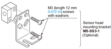
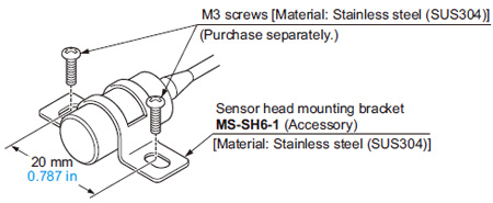
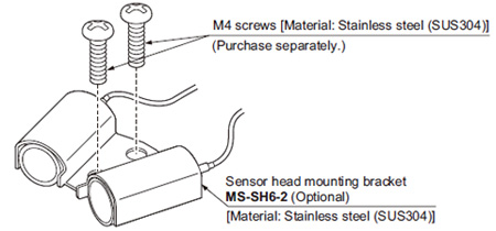
Mounting
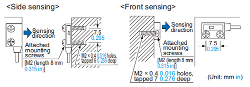
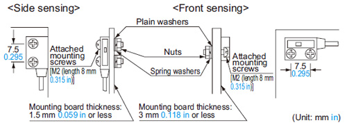
Ultra-slim type
- With tapped screws
|
|
|
|
|
In case of chemical resistant type sensor head
- Do not use where it can be exposed to molten alkali metals (sodium, potassium, lithium, etc.), fluorine gas (F2), CIF3, OF2 (including gaseous state), etc.
- In case of cable extension, the extended portion should be placed in an area where it is not exposed to chemicals.
Amplifier
Wiring
- The self-diagnosis output does not incorporate a shortcircuit protection circuit. Do not connect it directly to a power supply or a capacitive load.
Sensitivity setting
・Normal sensitivity setting
| Standard setting |
|---|
The sensor recognizes the ON (object present) and OFF (object absent) levels by your pressing of the buttons. The threshold level is automatically set at the middle between ON and OFF levels.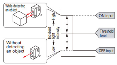 |
・Maximum sensitivity setting
| Full power setting |
|---|
 The maximum sensitivity is set. Take care that, in case of the diffuse reflective type, if a background object is present, the sensing output may turn ON even without the sensing object. The maximum sensitivity is set. Take care that, in case of the diffuse reflective type, if a background object is present, the sensing output may turn ON even without the sensing object. |
*How to set sensitivity with external inputs
| Remote sensitivity setting (SU-77 only) |
|---|
| Instead of pressing buttons, the sensitivity can be set with the remote sensitivity setting inputs. (There is no external sensitivity shift mode.) Setting procedure The procedure is the same as for setting with sensitivity buttons, except that instead of pressing the buttons, the remote sensitivity setting input wire is shortcircuited to 0 V. The mode selection switch is set to either the “SET” or “RUN” side. 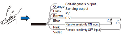 ・Time chart The self-diagnosis output stays ON for 40 ms approx. after ON input or OFF input is recognized by the sensor. (If the difference between the ON and OFF levels (the difference between incident light levels) is so small that stable detection is not possible, it does not turn ON.) 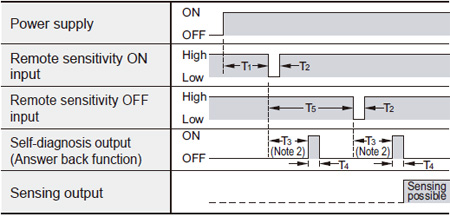 T1≥1,000ms、3,000ms>T2≥5ms、T3≈310ms、T4≈40ms、T5≥500ms Notes: 1)Signal condition ... Low: 0 to 1 V, High: 4.5 to 30 V, or open Input impedance: 10 kΩ 2):Do not move the object, etc., or change the incident light intensity during T3. |
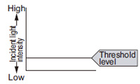
・Sensitivity for detecting minute differences
| Limit sensitivity setting |
|---|
| Setting for minute detection is possible just by pressing a button once without the object being present. For detecting a tiny object For stable detection of an object without detecting the background 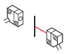 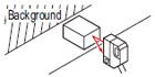 By pressing either ON or OFF button for 3 sec. or more, the threshold level is set 15 % either lower or higher than the object absent level as shown in the right figure. 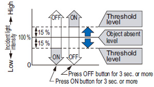 (Please note that the output
operation cannot be reversed.) (Please note that the output
operation cannot be reversed.)For example, press the ON button for detecting a tiny object. |
・For applications in which beam intensity fluctuates
| Sensitivity shift |
|---|
| If the incident light is stable in either the object present or object absent state, by shifting the threshold level towards this state, stable sensing is possible even if the incident light is unstable in the other state. The setting level is the same as for limit sensitivity setting. However, since the operating level is shifted after the normal sensitivity setting, output operation is selectable. Setting procedure Press the sensitivity setting button which was pressed in the stable light received condition. For example, for a diffuse reflective type sensor, in case a background object is present, press the button which was pressed with only the background object being sensed. 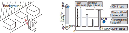 |
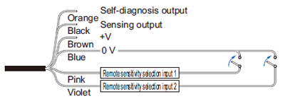
Remote sensitivity selection function (SU-79 only)
- SU-79 can store four channels of sensitivity levels, which can be selected as per your requirement. Designate the channel that is to store the sensitivity by making the remote sensitivity selection inputs 1 and 2 suitably High or Low.
|
Signal condition Channel selection
|
Low: 0 to 1 V |
| Input | Remote sensitivity selection input 1 | Remote sensitivity selection input 2 | |
|---|---|---|---|
| Channel | |||
| 1 | Low | Low | |
| 2 | Low | High | |
| 3 | High | Low | |
| 4 | High | High | |
External synchronization function (SU-75 only)
- The external synchronization function can be used to control the timing of sensing. Edge trigger or gate trigger are available.
|
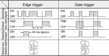
T≥0.6ms(T≧0.8ms when the interference prevention function is used)
| Note: | The external synchronization selection switch must be turned fully clockwise or counterclockwise. |
|---|
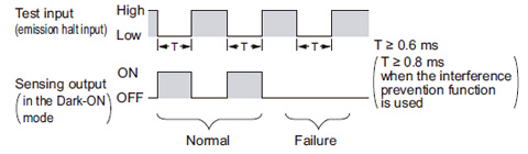
Test input (emission halt) function (SU-75 only)
- When the test input (emission halt input) (violet) is shortcircuited to 0 V (Low), the beam emission is halted. This function is useful for a start-up test since the sensing output can be made ON / OFF without the sensing object. Short-circuit to 0 V and open the input, repeatedly. If the sensing output follows this operation, the sensor is working well, else not.
|
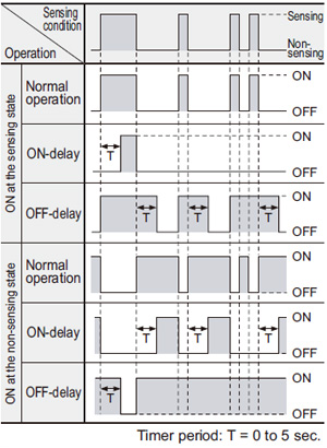
Timer function (Excluding SU-75)
- Every SU-7 series amplifier (excluding SU-75) is incorporated with a variable ON / OFF delay timer for 0 to 5 sec.
ON-delay OFF-delay |
 |
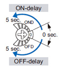
- Timer period setting
Adjust the time duration of ON or OFF delay by turning the timer adjuster.
|
 |
Self-diagnosis function
- The sensor checks the incident light intensity, and if it is reduced due to dirt or dust, or beam misalignment, an output is generated.
|
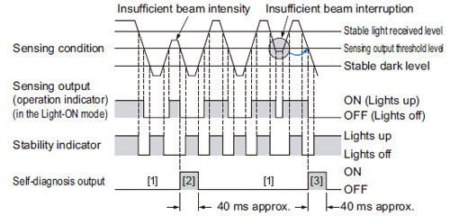
| [1] | The self-diagnosis output transistor stays in the “OFF” state during stable sensing. |
|---|---|
| [2] | When the sensing output changes, if the incident light intensity does not reach the stable light received level or the stable dark level, the self-diagnosis output becomes ON. It is automatically restored after 40 ms approx. Further, the self-diagnosis output changes state when the sensing output changes from Light to Dark state. It is not affected by the output operation of the sensing output. |
| [3] | In case of insufficient beam interruption, there will be a time lag before the self-diagnosis output turns ON. |
Others
- Do not use during the initial transient time (0.5 sec.) after the power supply is switched on.
Use conditions to comply with CE Marking
(SH-3□ only)
- Following work must be done in cace of using this product as a CE marking (European standard EMC Directive) conforming product.
Place ferrite core at the sensor cable.
|
|
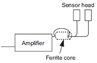
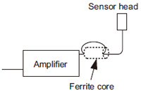
Place a ferrite core near the amplifier.
In that condition, the sensor head cable should be single-winding.
Prepare 1 pc. of the following recommended ferrite core (or an equivalent product.)
<Recommended product>
ESD-SR-110 [NEC TOKIN Corporation]
BY EMAIL
- U.S.A.
- +1-800-344-2112
- Europe
- +49-89-45354-1000
- China
- +86-10-59255988
- Singapore
- +65-6299-9181


Requests to customers (Automation Control Components & Industrial Device) [Excluding specific product]
Requests to customers (Automation Control Components & Industrial Device) [For specific product]
Requests to customers (FA Sensors & Components [Excluding motors])
Requests to customers (Dedicated to industrial motors)
- COMPONENTS & DEVICES
- FA SENSORS & COMPONENTS
- Fiber Sensors
- Photoelectric Sensors / Laser Sensors
- Micro Photoelectric Sensors
- Light Curtains / Safety Components
- Area Sensors
- Inductive Proximity Sensors
- Particular Use Sensors
- Sensor Options
- Wire-Saving Systems
- Programmable Controllers / Interface Terminal
- Human Machine Interface
- Pressure Sensors / Flow Sensors
- Measurement Sensors
- Static Control Devices
- Laser Markers / 2D Code Readers
- Machine Vision System
- Energy Management Solutions
- Timers / Counters / FA Components
- MOTORS
![]()