【Notification of Manufacturer Change for Panasonic Industrial Devices SUNX Products and Panasonic Industrial Devices SUNX Tatsuno Products】
From April 1, 2024, the terms "Panasonic Industrial Devices SUNX Co., Ltd." and "Panasonic Industrial Devices SUNX Tatsuno Co., Ltd."
in this page and in the manuals and other documents to be downloaded will all be replaced with "Panasonic Industry Co., Ltd." and applied accordingly.

 Business
> Industrial Devices
> Automation Controls Top
> FA Sensors & Components
> Sensors
> Light Curtains / Safety Components
> Exclusive Control Unit for Safety Light Curtain SF-C10
> Cautions For Use
Business
> Industrial Devices
> Automation Controls Top
> FA Sensors & Components
> Sensors
> Light Curtains / Safety Components
> Exclusive Control Unit for Safety Light Curtain SF-C10
> Cautions For Use
Exclusive Control Unit for Safety Light Curtain SF-C10
|
Partly Order Discontinued
|
Cautions For Use
Part description and function [SF-C14EX(-01)]
|
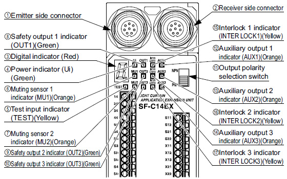
| No. | Description | Function |
|---|---|---|
| ① | Emitter side connector | The emitter of SF4B / SF4B-G series is connected. |
| ② | Receiver side connector | The receiver of SF4B / SF4B-G series is connected. |
| ③ | Digital indicator (Red) | Lights up or blinks when there is a problem. Lights up when blanking function is enabled. |
| ④ | Power indicator (Ui) (Green) | Lights up when the power is ON. |
| ⑤ | Test input indicator (TEST) (Yellow) | Lights up when test input is enabled. Blinks while communication with SFB-HC (optional) handy-controller is in progress. (Excluding SF-C14EX-01) |
| ⑥ | Muting sensor 1 indicator (MU1) (Orange) | Lights up when muting sensor 1 is ON. |
| ⑦ | Muting sensor 2 indicator (MU2) (Orange) | Lights up when muting sensor 2 is ON. |
| ⑧ | Safety output 1 indicator (OUT1) (Green) | Lights up when safety output 1 is ON. |
| ⑨ | Safety output 2 indicator (OUT2) (Green) | Lights up when safety output 2 is ON. |
| ⑩ | Safety output 3 indicator (OUT3) (Green) | Lights up when safety output 3 is ON. |
| ⑪ | Output polarity selection switch | PNP (minus ground) or NPN (plus ground) can be selected. The factory setting is PNP (minus ground). |
| ⑫ | Auxiliary output 1 indicator (AUX1) (Orange) | Lights up when auxiliary output 1 is ON. |
| ⑬ | Auxiliary output 2 indicator (AUX2) (Orange) | Lights up when auxiliary output 2 is ON. |
| ⑭ | Auxiliary output 3 indicator (AUX3) (Orange) | Lights up when auxiliary output 3 is ON. |
| ⑮ | Interlock 1 indicator (INTER LOCK1) (Yellow) | Lights up when interlock 1 is ON. |
| ⑯ | Interlock 2 indicator (INTER LOCK2) (Yellow) | Lights up when interlock 2 is ON. |
| ⑰ | Interlock 3 indicator (INTER LOCK3) (Yellow) | Lights up when interlock 3 is ON. |
Wiring
- The following solid wire and twisted wires (lead wire) are recommended.
SF-C11
Power supply and output line connector : 0.2 to 2.5mm2 (AWG24 to 12)
Signal line connector : 0.2 to 1.5mm2 (AWG24 to 16)
SF-C13
Single wire : ø0.4 to ø1.2mm ø0.016 to ø0.047 in (AWG26 to 16)
Twisted wire (lead wire) : 0.3 to 1.25mm2(AWG22 to 16)
SF-C14EX(-01)
Power supply line connector (A1, A2) : 0.2 to 2.5mm2(AWG24 to 12)
Other connectors ; 0.2 to 1.5mm2 (AWG24 to 16)
Output waveform (Safety output ON) [SF-C14EX(-01)]
- When safety output is ON, self-diagnosis of the output circuit is carried out, so that the output transistor will periodically turn OFF. (OFF pulse width: 100 μs or less) When the OFF signal is fed back, the receiver judges the output circuit as normal. When the OFF signal is not fed back, the receiver judges either the output circuit or wiring as error, and the safety output maintains OFF status.
- Since the OFF signal of SF-C14EX(-01) might cause malfunction, perform the connecting paying attention to the input response time of the machine to be connected to SF-C14EX(-01).
Time chart [SF-C14EX(-01)]
| Normal operation |
- The diagram shows operation with safety outputs 1 and 2 in manual-reset mode.
|
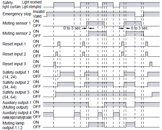
- The diagram above is the timing chart of SF-C14EX(-01) in normal operation.
- In normal operation, auxiliary output 2 (override output) is maintained in the ON state.
- In normal operation, auxiliary output 3 (muting lamp output) is maintained in the ON state.
Time chart [SF-C14EX(-01)]
| Test input, Override input |
- The diagram shows operation with safety outputs 1 and 2 in auto-reset mode.
|
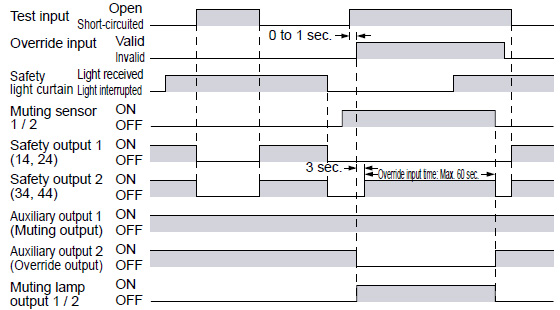
- Safety outputs 1 and 2 are OFF during test input.
- The override function becomes valid when all the conditions listed below are satisfied:
• An incandescent lamp with 3.6 to 30 W is at least connected to either muting lamp output 1 or 2.
• The signal is input to either muting sensor 1 or 2.
• The override input terminal O1 and O2 is short-circuited and the test input terminal T1 / T2 is opened within 1 sec. (3 sec. continuously)
If one of the three conditions above becomes invalid or the timing exceeds 60 sec., the override function becomes invalid.
Blown lamp output
- The diagram shows operation with safety outputs 1 and 2 in auto-reset mode.
|
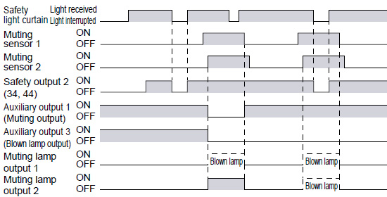
- The lamps are monitored during muting state, and if either of them breaks, auxiliary output 3 is turned OFF. If only one lamp breaks, the muting state is maintained, however, if both lamps break, the muting state is canceled immediately.
Others
- This device has been developed / produced for industrial use only.
- When connecting this product to a product other than the connectable input device, the system does not conform to the control category 4 based on ISO 13849-1
(EN ISO 13849-1, JIS B 9705-1). - The power supply unit of SF-C10 series uses the electronic fuse which does not require any replacement.
- When the electronic fuse trips, turn off the power supply and eliminate the cause for the overcurrent. After that, turn the power back on.
- The electronic fuse is not meant to be used for equipment that is operated continuously. Note that the specification may not be satisfied by continuous operation.
- Make sure to carry out the wiring in the power supply off condition.
- Wrong wiring will damage the product.
- Verify that the supply voltage variation is within the rating. Note that if a voltage exceeding the rated range is applied, or if an AC power supply is directly connected, the unit may get burnt or damaged.
- The DC power supply unit must satisfy the conditions given below:
1) Power supply unit authorized in the region where this device is to be used.
2) Power supply unit conforming to EMC Directive and Low-voltage Directive (In case CE conformity is required.)
3) Power supply unit conforming to EMC Regulations and Low-voltage Regulations (In case UKCA conformity is required.)
4) Power supply unit conforming to the Low-voltage Directive and with an output of 100 VA or less.
5) The frame ground (F.G.) terminal must be connected to ground when using a commercially available switching regulator.
6) Power supply unit with an output holding time of 20 ms or more.
7) Use an isolation transformer for the DC power supply unit.
8) If surges are likely to occur, take countermeasures such as connecting a surge absorber to the origin of the surge.
9) Power supply unit corresponding to CLASS 2 (In case UL/c-UL conformity is required.)
<Additional information>
As provided in IEC 60536 (CLASS: Protection against Electric Shook), this power supply should require no ground earth and satisfy the insulation distance by double insulation or reinforced insulation.
(If the power supply conforms to Low-voltage Directive and has an output of 100 VA or less, it can be used as a suitable product.) - Do not run the wires together with high-voltage lines or power lines or put them in the same raceway. This can cause malfunction due to induction.
- This product is not dust-proof / splash proof. Be sure to put this product into a control box having IP54 construction. (Excluding SF-C12)
- Avoid dust, dirt and steam.
- Take care that the product does not come in direct contact with oil, grease, or organic solvents, such as, thinner, etc.
- Note that this equipment is applicable only in the control circuit grounded in accordance with IEC 60204-1 and JIS B 9960-1, or in the control circuit in which the insulation monitor unit (ground fault detection unit) is included.
- This unit is suitable for indoor use only.
- The seal as shown in the drawing on the below is stuck to the engagement point of unit. If the seal is peeled off or broken, SF-C10 series will not be certified as “Safety equipment” and will not be covered by our guarantee.
|
BY EMAIL
- U.S.A.
- +1-800-344-2112
- Europe
- +49-89-45354-1000
- China
- +86-10-59255988
- Singapore
- +65-6299-9181


Requests to customers (Automation Control Components & Industrial Device) [Excluding specific product]
Requests to customers (Automation Control Components & Industrial Device) [For specific product]
Requests to customers (FA Sensors & Components [Excluding motors])
Requests to customers (Dedicated to industrial motors)
- COMPONENTS & DEVICES
- FA SENSORS & COMPONENTS
- Fiber Sensors
- Photoelectric Sensors / Laser Sensors
- Micro Photoelectric Sensors
- Light Curtains / Safety Components
- Area Sensors
- Inductive Proximity Sensors
- Particular Use Sensors
- Sensor Options
- Wire-Saving Systems
- Programmable Controllers / Interface Terminal
- Human Machine Interface
- Pressure Sensors / Flow Sensors
- Measurement Sensors
- Static Control Devices
- Laser Markers / 2D Code Readers
- Machine Vision System
- Energy Management Solutions
- Timers / Counters / FA Components
- MOTORS
![]()