【Notification of Manufacturer Change for Panasonic Industrial Devices SUNX Products and Panasonic Industrial Devices SUNX Tatsuno Products】
From April 1, 2024, the terms "Panasonic Industrial Devices SUNX Co., Ltd." and "Panasonic Industrial Devices SUNX Tatsuno Co., Ltd."
in this page and in the manuals and other documents to be downloaded will all be replaced with "Panasonic Industry Co., Ltd." and applied accordingly.
Safety Light Curtain Type 2 SF2B Ver.2 (Discontinued Products)
We are sorry, the products have been discontinued. Please refer to the details of the discontinued products and the recommended substitutes list below.
|
|
I/O Circuit and Wiring diagrams
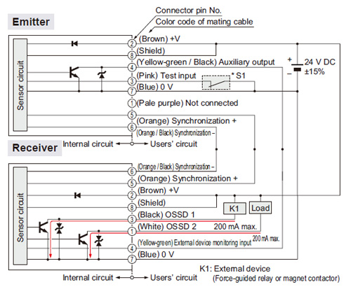
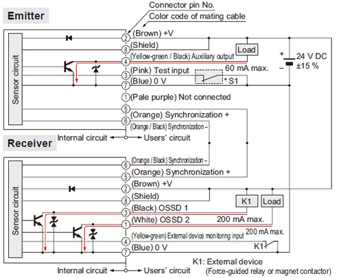
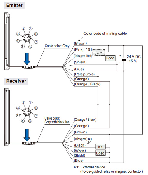
NPN output type
| When using a SF2B-CCB□ or SF2B-CB□ bottom cap cable |
I/O circuit diagram
<In case of setting the external device monitoring function to enabled> |
 |
|
| Note: |
Unused wires must be insulated to ensure that they do not come into contact with wires already in use. |
CAUTION
Construct the interlock (reset input) circuit separately. |
*S1
| Switch S1 |
| ・ |
Test input
Open: Emission halt
0 to +1.5 V (source current 5 mA or less): Emission |
Wiring diagram
<In case of setting the external device monitoring function to enabled> |
 |
|
| Note: |
Unused wires must be insulated to ensure that they do not come into contact with wires already in use. |
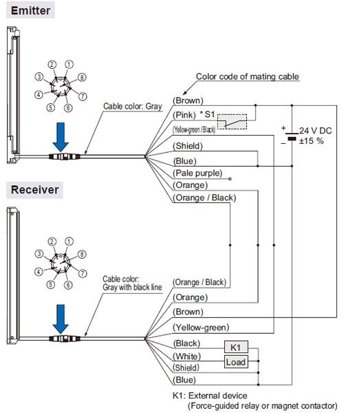
I/O circuit diagram
<In case of setting the external device monitoring function to disabled>
- In order to disable the external device monitoring function, connect the auxiliary output and external device monitoring input. At such times, do not connect a load to the auxiliary output.
| Note: |
Unused wires must be insulated to ensure that they do not come into contact with wires already in use. |
CAUTION
Construct the interlock (reset input) circuit separately. |
*S1
| Switch S1 |
| ・ |
Test input
Open: Emission halt
0 to +1.5 V (source current 5 mA or less): Emission |
Wiring diagram
<In case of setting the external device monitoring function to disabled> |
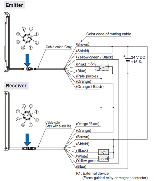 |
|
| Note: |
Unused wires must be insulated to ensure that they do not come into contact with wires already in use. |
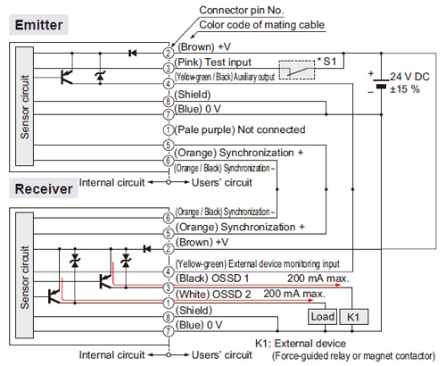
PNP output type
| When using a SF2B-CCB□ or SF2B-CB□ bottom cap cable |
I/O circuit diagram
<In case of setting the external device monitoring function to enabled> |
 |
|
| Note: |
Unused wires must be insulated to ensure that they do not come into contact with wires already in use. |
CAUTION
Construct the interlock (reset input) circuit separately. |
*S1
| Switch S1 |
| ・ |
Test input
Open: Emission halt
Vs to Vs – 2.5 V (sink current 5 mA or less): Emission (Note 2) |
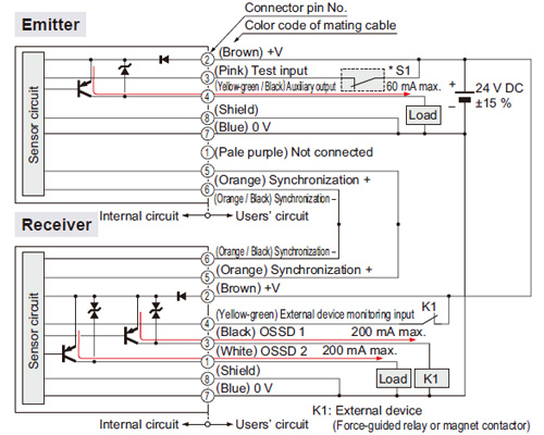
Notes:
| 1) |
Unused wires must be insulated to ensure that they do not come into contact with wires already in use. |
| 2) |
Vs is the applying supply voltage. |
Wiring diagram
<In case of setting the external device monitoring function to enabled> |
 |
|
| Note: |
Unused wires must be insulated to ensure that they do not come into contact with wires already in use. |
I/O circuit diagram
<In case of setting the external device monitoring function to disabled>
- In order to disable the external device monitoring function, connect the auxiliary output and external device monitoring input. At such times, do not connect a load to the auxiliary output.
CAUTION
Construct the interlock (reset input) circuit separately. |
*S1
| Switch S1 |
| ・ |
Test input
Open: Emission halt
Vs to Vs – 2.5 V (sink current 5 mA or less): Emission (Note 2) |
Notes:
| 1) |
Unused wires must be insulated to ensure that they do not come into contact with wires already in use. |
| 2) |
Vs is the applying supply voltage. |
Wiring diagram
<In case of setting the external device monitoring function to disabled> |
 |
|
| Note: |
Unused wires must be insulated to ensure that they do not come into contact with wires already in use. |
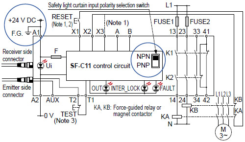
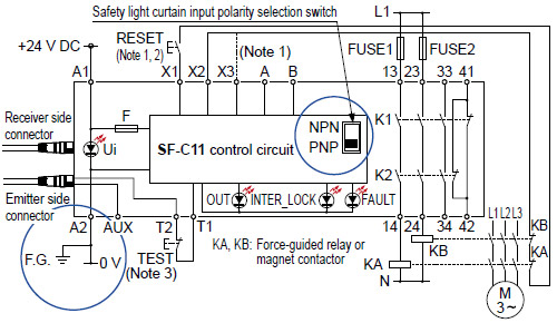
SF-C11
SF2B series wiring diagram (Control category 2)
| For NPN output (plus ground) |
- Set the safety light curtain input polarity selection switch to the NPN side and ground the + side.
Notes:
| 1) |
The above diagram is when using manual reset. If automatic reset is used, disconnect the lead from X2 and connect it to X3. In this case, a reset (RESET) button is not needed. |
| 2) |
Use a momentary-type switch as the reset (RESET) button. |
| 3) |
Emission halt occurs when the test (TEST) button is open, and emission occurs when the test (TEST) button is short-circuited. If not using the test (TEST) button, short-circuit T1 and T2. However, use a test rod or similar to interrupt the light in order to carry out self-diagnosis separately. |
| For PNP output (minus ground) |
- Set the safety light curtain input polarity selection switch to the PNP side and ground the 0 V line.
Notes:
| 1) |
The above diagram is when using manual reset. If automatic reset is used, disconnect the lead from X2 and connect it to X3. In this case, a reset (RESET) button is not needed. |
| 2) |
Use a momentary-type switch as the reset (RESET) button. |
| 3) |
Emission halt occurs when the test (TEST) button is open, and emission occurs when the test (TEST) button is short-circuited. If not using the test (TEST) button, short-circuit T1 and T2. However, use a test rod or similar to interrupt the light in order to carry out self-diagnosis separately. |
Be sure to use the following mating cables when connecting SF-C11 to
SF2B series.
SF2B-CB05 (cable length: 0.5 m 1.640 ft)
SF2B-CB5 (cable length: 5 m 16.404 ft)
SF2B-CB10 (cable length: 10 m 32.808 ft)
SFB-CCJ10E (for emitter, cable length: 10 m 32.808 ft)
SFB-CCJ10D (for receiver, cable length: 10 m 32.808 ft)
|
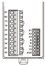
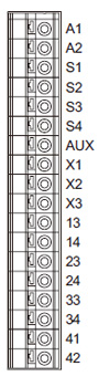
Terminal arrangement diagram
|
|
| Terminal |
Function |
| A1 |
+24 V DC |
| A2 |
0 V |
13-14, 23-24,
33-34 |
Safety output
(NO contact × 3) |
| 41-42 |
Auxiliary output (NC contact × 1) |
| X1 |
Reset output terminal |
| X2 |
Reset input terminal (Manual) |
| X3 |
Reset input terminal (Automatic) |
| A |
Not used |
| B |
| T1 |
Test output terminal |
| T2 |
Test input terminal |
| AUX |
Semiconductor auxiliary output |
|
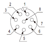
Pin layout for safety light curtain connectors
|
|
| Connector pin No. |
Emitter side connector |
Receiver side connector |
| 1 |
Not used |
OSSD2 |
| 2 |
+24 V DC |
+24 V DC |
| 3 |
Emission halt |
OSSD1 |
| 4 |
Auxiliary output |
EDM (External relay monitor) |
| 5 |
Synchronization wire + |
Synchronization wire + |
| 6 |
Synchronization wire – |
Synchronization wire – |
| 7 |
0 V |
0 V |
| 8 |
Shield wire |
Shield wire |
|
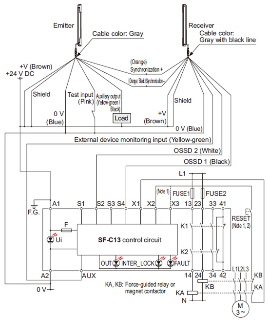
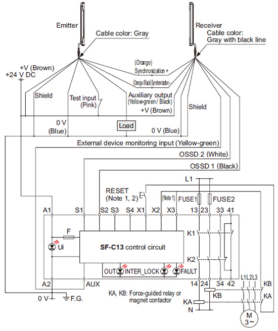
SF-C13
SF2B series wiring diagram (Control category 2)
- Connect the safety light curtain control outputs OSSD 1 and OSSD 2 to S4 and S2 respectively and ground the + side.
Notes:
| 1) |
The left diagram is when using manual reset. If automatic reset is used, disconnect the lead from X2 and connect it to X3. In this case, a reset (RESET) button is not needed. |
| 2) |
Use a momentary-type switch as the reset (RESET) button. |
- Connect the safety light curtain control outputs OSSD 1 and OSSD 2 to S1 and S2 respectively.
Notes:
| 1) |
The left diagram is when using manual reset. If automatic reset is used, disconnect the lead from X2 and connect it to X3. In this case, a reset (RESET) button is not needed. |
| 2) |
Use a momentary-type switch as the reset (RESET) button. |
Terminal arrangement diagram
|
|
| Terminal |
Function |
| A1 |
+24 V DC |
| A2 |
0 V |
| S1 to S4 |
Safety light curtain control output
(OSSD) input terminal |
| AUX |
Semiconductor auxiliary output |
| X1 |
Reset output terminal |
| X2 |
Reset input terminal (Manual) |
| X3 |
Reset input terminal (Automatic) |
13-14, 23-24,
33-34 |
Safety output
(NO contact × 3) |
| 41-42 |
Auxiliary output (NC contact × 1) |
|
| |
Use a separate terminal block to carry out wiring for
safety light curtains that cannot be connected to the SF-C13. |
|
Return to top
Return to top

 Business
> Industrial Devices
> Automation Controls Top
> FA Sensors & Components
> Sensors
> Light Curtains / Safety Components
> Safety Light Curtain Type 2 SF2B Ver.2(Discontinued Products)
> I/O Circuit and Wiring diagrams
Business
> Industrial Devices
> Automation Controls Top
> FA Sensors & Components
> Sensors
> Light Curtains / Safety Components
> Safety Light Curtain Type 2 SF2B Ver.2(Discontinued Products)
> I/O Circuit and Wiring diagrams