【Notification of Manufacturer Change for Panasonic Industrial Devices SUNX Products and Panasonic Industrial Devices SUNX Tatsuno Products】
From April 1, 2024, the terms "Panasonic Industrial Devices SUNX Co., Ltd." and "Panasonic Industrial Devices SUNX Tatsuno Co., Ltd."
in this page and in the manuals and other documents to be downloaded will all be replaced with "Panasonic Industry Co., Ltd." and applied accordingly.
Compact Type 4 Safety Beam Sensor ST4
Cautions For Use
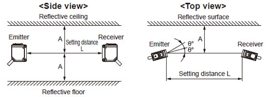
Influence of reflective surfaces
- If there exists a reflective surface in the place where this device is to be installed, make sure to install this device so that reflected light from the reflective surface does not enter into the receiver, or take countermeasures such as painting, masking, roughening, or changing the material of the reflective surface, etc. Failure to do so may cause the device not to detect, resulting in death or serious injury.
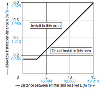
- Install this device at a distance of at least A (m) (given below) away from reflective surfaces such as metal walls, floors, ceilings, objects, covers, panels or glass surfaces.
Distance between emitter and receiver
(Setting distance L) |
Allowable installation distance A |
| 0.1 to 3 m 0.328 to 9.843 ft |
0.16 m 0.525 ft |
| 3 to 15 m 9.843 to 49.213 ft |
L/2×tan2θ=L×0.053(m) 0.174 (ft) ((θ=3°) |
| Note: |
The effective aperture angle for this device is ±2.5° (when L > 3 m 9.843 ft) as required by IEC 61496-2 / UL 61496-2. However, install this device away from reflective surfaces considering an effective aperture angle of ±3° to take care of beam misalignment, etc. during
installation. |
<Allowable installation distance between reflective surfaces and beam axis of receiver> |
 |
|
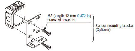
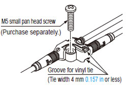
Mounting
- When mounting the sensor head, the tightening torque should be 0.5 N·m or less.
- When mounting ST4-CCJ05-WY, the tightening torque should be 0.7 N·m or less. Using a vinyl tie (width 4 mm 0.157 in or less) to fix the cable is also possible.
Wiring
- Refer to the applicable regulations for the region where this device is to be used when setting up the device. In addition, make sure that all necessary measures are taken to prevent possible dangerous operating errors resulting from earth faults.
- Make sure to carry out the wiring in the power supply off condition.
- Verify that the supply voltage variation is within the rating.
- If power is supplied from a commercial switching regulator, ensure that the frame ground (F.G.) terminal of the power supply is connected to an actual ground.
- In case noise generating equipment (switching regulator, inverter motor, etc.) is used in the vicinity of this sensor and controller, connect the frame ground (F.G.) terminal of the equipment to an actual ground.
- Do not run the wires together with high-voltage lines or power lines or put them in the same raceway. This can cause malfunction due to induction.
- It is recommended that the following single wires or twisted wires (lead wires) be used to connect to the terminal block of the controller.
・ Terminal block connector: 0.2 to 1.5 mm2 (AWG24 to AWG16)
・ Power supply connector (A1, A2) (ST4-C12EX only): 0.2 to 2.5 mm2 (AWG24 to AWG12)
Others
- This device has been developed / produced for industrial use only.
- Do not use during the initial transient time (2 sec.) after the power supply is switched on.
- Avoid dust, dirt and steam.
- Take care that the sensor does not come in direct contact with water, oil, grease, or organic solvents, such as, thinner, etc.
- Take care that the sensor is not directly exposed to fluorescent lamp from a rapid-starter lamp or a high frequency lighting device, as it may affect the sensing performance.
- Do not use this product with mobile equipment such as an automated guided vehicle (AGV).
- The DC power supply unit must satisfy the conditions given below.
| 1) |
Power supply unit authorized in the region where this devices is to be used. |
| 2) |
Power supply unit conforming to EMC Directive and Lowvoltage Directive (In case CE conformity is required). |
| 3) |
Power supply unit conforming to EMC Regulations and Lowvoltage Regulations (In case UKCA conformity is required). |
| 4) |
Power supply unit conforming to the Low-voltage Directive and with an output of 100 VA or less. |
| 5) |
The frame ground (F.G.) terminal must be connected to ground when using a commercially available switching regulator. |
| 6) |
Power supply unit with an output holding time of 20 ms or more. |
| 7) |
If surges are likely to occur, take countermeasures such as connecting a surge absorber to the origin of the surge. |
| 8) |
Power supply unit corresponding to Class 2 (In case UL / cUL conformity is required). |
Return to top
Return to top

 Business
> Industrial Devices
> Automation Controls Top
> FA Sensors & Components
> Sensors
> Light Curtains / Safety Components
> Compact Type 4 Safety Beam Sensor ST4
> Cautions For Use
Business
> Industrial Devices
> Automation Controls Top
> FA Sensors & Components
> Sensors
> Light Curtains / Safety Components
> Compact Type 4 Safety Beam Sensor ST4
> Cautions For Use