【Notification of Manufacturer Change for Panasonic Industrial Devices SUNX Products and Panasonic Industrial Devices SUNX Tatsuno Products】
From April 1, 2024, the terms "Panasonic Industrial Devices SUNX Co., Ltd." and "Panasonic Industrial Devices SUNX Tatsuno Co., Ltd."
in this page and in the manuals and other documents to be downloaded will all be replaced with "Panasonic Industry Co., Ltd." and applied accordingly.
Compact Type 4 Safety Beam Sensor ST4
I/O Circuit and Wiring diagrams
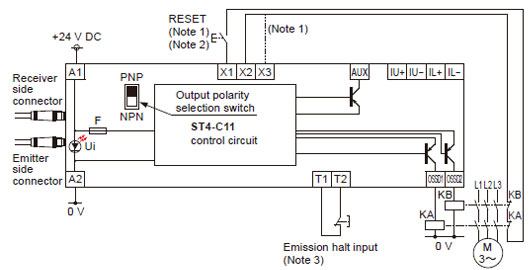
ST4-C11
In case of PNP output
・Set the output polarity selection switch to the PNP side. |
 |
|
Notes:
| 1) |
The left diagram is when using manual reset. If automatic reset is used, disconnect the lead from X2 and connect it to X3. In this case, a reset (RESET) button is not needed. |
| 2) |
Use a momentary-type switch as the reset (RESET) button. |
| 3) |
Emission halt input is for stopping emission when open, and emitting when short-circuited. If not using the test button, short-circuit T1 and T2. |
| KA, KB: |
Force-guided relay or magnetic contactor |
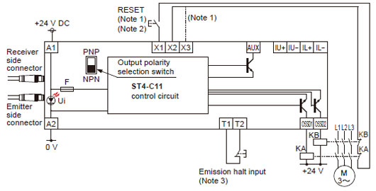
In case of NPN output
・Set the output polarity selection switch to the NPN side. |
 |
|
Notes:
| 1) |
The left diagram is when using manual reset. If automatic reset is used, disconnect the lead from X2 and connect it to X3. In this case, a reset (RESET) button is not needed. |
| 2) |
Use a momentary-type switch as the reset (RESET) button. |
| 3) |
Emission halt input is for stopping emission when open, and emitting when short-circuited. If not using the test button, short-circuit T1 and T2. |
| KA, KB: |
Force-guided relay or magnetic contactor |
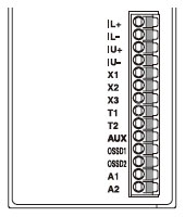
Terminal arrangement diagram
|
|
| Terminal |
Description |
| IL+ |
Interference prevention terminals |
| IL- |
| IU+ |
Interference prevention terminals |
| IU- |
| X1 |
Reset input terminals
(When X1 and X2 are connected: manual reset, and
when X1 and X3 are connected: auto reset) |
| X2 |
| X3 |
| T1 |
Emission halt input terminals
(Open: emission halt, Short-circuit: emission) |
| T2 |
| AUX |
Negative logic of the control outputs
(OSSD1, OSSD2) |
| OSSD1 |
Control outputs (OSSD1, OSSD2) |
| OSSD2 |
| A1 |
24V DC |
| A2 |
0V |
|
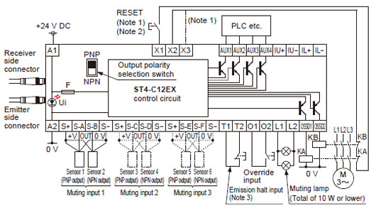
ST4-C12EX
In case of PNP output
・Set the output polarity selection switch to the PNP side. |
 |
|
Notes:
| 1) |
The left diagram is when using manual reset. If automatic reset is used, disconnect the lead from X2 and connect it to X3. In this case, a reset (RESET) button is not needed. |
| 2) |
Use a momentary-type switch as the reset (RESET) button. |
| 3) |
Emission halt input is for stopping emission when open, and emitting when short-circuited. If not using the test button, short-circuit T1 and T2. |
| KA, KB: |
Force-guided relay or magnetic contactor |
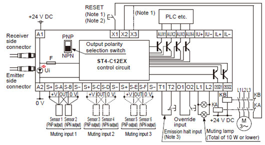
In case of NPN output
・Set the output polarity selection switch to the NPN side. |
 |
|
Notes:
| 1) |
The left diagram is when using manual reset. If automatic reset is used, disconnect the lead from X2 and connect it to X3. In this case, a reset (RESET) button is not needed. |
| 2) |
Use a momentary-type switch as the reset (RESET) button. |
| 3) |
Emission halt input is for stopping emission when open, and emitting when short-circuited. If not using the test button, short-circuit T1 and T2. |
| KA, KB: |
Force-guided relay or magnetic contactor |
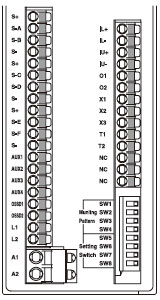
Terminal arrangement diagram
|
|
| Terminal |
Description |
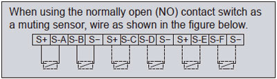
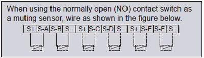
| S+ |
Muting input power supply (24 V) |
| S-A |
Muting input S-A [For NO (nomally open) contact or PNP output type sensor] |
| S-B |
Muting input S-B [For NO (nomally open) contact or NPN output type sensor] |
| S- |
Muting input power supply (0 V) |
| S+ |
Muting input power supply (24 V) |
| S-C |
Muting input S-C [For NO (nomally open) contact or PNP output type sensor] |
| S-D |
Muting input S-D [For NO (nomally open) contact or NPN output type sensor] |
| S- |
Muting input power supply (0 V) |
| S+ |
Muting input power supply (24 V) |
| S-E |
Muting input S-E [For NO (nomally open) contact or PNP output type sensor] |
| S-F |
Muting input S-F [For NO (nomally open) contact or NPN output type sensor] |
| S- |
Muting input power supply (0 V) |
| AUX1 |
Auxiliary output 1 (muting function) |
| AUX2 |
Auxiliary output 2 (override function) |
| AUX3 |
Auxiliary output 3 (muting lamp shutoff) |
| AUX4 |
Negative logic of the control outputs (OSSD1, OSSD2) |
| OSSD1 |
Control outputs (OSSD1, OSSD2) |
| OSSD2 |
| L1 |
Muting lamp connecting terminal |
| L2 |
| A1 |
24V DC |
| A2 |
0V |
| IL+ |
Interference prevention terminals |
| IL- |
| IU+ |
Interference prevention terminals |
| IU- |
| O1 |
Override input terminals |
| O2 |
| X1 |
Reset input terminals
(When X1 and X2 are connected: manual reset, and
when X1 and X3 are connected: auto reset) |
| X2 |
| X3 |
| T1 |
Emission halt input terminals
(Open: emission halt, Short-circuit: emission) |
| T2 |
|
Return to top
Return to top

 Business
> Industrial Devices
> Automation Controls Top
> FA Sensors & Components
> Sensors
> Light Curtains / Safety Components
> Compact Type 4 Safety Beam Sensor ST4
> I/O Circuit and Wiring diagrams
Business
> Industrial Devices
> Automation Controls Top
> FA Sensors & Components
> Sensors
> Light Curtains / Safety Components
> Compact Type 4 Safety Beam Sensor ST4
> I/O Circuit and Wiring diagrams