【Notification of Manufacturer Change for Panasonic Industrial Devices SUNX Products and Panasonic Industrial Devices SUNX Tatsuno Products】
From April 1, 2024, the terms "Panasonic Industrial Devices SUNX Co., Ltd." and "Panasonic Industrial Devices SUNX Tatsuno Co., Ltd."
in this page and in the manuals and other documents to be downloaded will all be replaced with "Panasonic Industry Co., Ltd." and applied accordingly.

 Business
> Industrial Devices
> Automation Controls Top
> FA Sensors & Components
> Sensors
> Light Curtains / Safety Components
> Optical Touch Switch SW-100
> Cautions For Use
Business
> Industrial Devices
> Automation Controls Top
> FA Sensors & Components
> Sensors
> Light Curtains / Safety Components
> Optical Touch Switch SW-100
> Cautions For Use
Optical Touch Switch SW-100
Cautions For Use
- Never use this product in a device for personnel protection.
- In case of using devices for personnel protection, use products which meet laws and standards, such as OSHA, ANSI or IEC etc., for personnel protection applicable in each region or country.
- Do not use this product as a device for emergency stop.
- This product is used to start up the machinery. Securing safety for the startup of machinery should be performed separately.
- When using the products for two-hand control, comply with the following contents.
- Select a model of a control device for two-hand control, based on results of risk assessment.
- Make sure to use a controller for two-hand control which complies with ISO 13851 (EN 574, JIS B 9712)
- For another requirements such as mounting of this product, or prevention of accidental actuation and of defeat etc., comply with ISO 13851 (EN 574, JIS B 9712) and ANSI B11.1, B11.9. Furthermore, comply with the regulations established by national or regional security committees (Occupational Safety and Health Administration: OSHA, the European Standardization Committee, etc.)
Mounting
- Fasten a mounting nut (accessory) from the reverse side of the mounting plate.(Note 1)
The tightening torque should be 2 to 3 N·m.
|
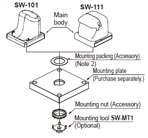
Notes:
| 1) | A mounting tool (SW-MT1) for fastening the mounting nut is available separately. The shape of fastening part of SW-MT1 is M10 nut. |
|---|---|
| 2) | Make sure to use the attached mounting packing, or waterproof property will be invalid. |
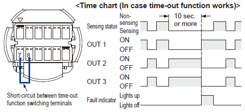
Time-out function
- Unintended beam interrupted status caused by dirt on the sensing surface, etc. can be monitored.
When beam interrupted status (sensing status) continues for 10 sec. or more, output 1 turns ON and output 2 and 3 turn OFF (output status is the same as non-sensing status.)
This function can be invalid by short-circuiting “between switching terminals of time-out function (terminal No. 7 and No. 8)” as described below.
| Note: | When time-out function is operated, the fault indicator (yellow) lights up. In this case, once beam is received, the fault indicator lights off and the sensor returns to normal operation. |
|---|
|
Others
- This device has been developed / produced for industrial use only.
- When the power of the thru-beam type photoelectric sensor inside the main body turns on in beam interrupted status, output 1 turns ON and output 2 and 3 turn OFF, then the fault indicator (yellow) lights up. In this case, once beam is received, the fault indicator lights off and the sensor returns to normal operation.
- Use a power supply unit conforming to the EMC Directive and the Low Voltage Directive. (Only for use in Europe)
- Use a power supply unit conforming to Class 2. (Only for use in the North America)
- Use a power supply unit with an output holding time of 20 ms or more.
- Do not use during the initial transient time (300 ms approx.) after the power supply is switched on.
BY EMAIL
- U.S.A.
- +1-800-344-2112
- Europe
- +49-89-45354-1000
- China
- +86-10-59255988
- Singapore
- +65-6299-9181


Requests to customers (Automation Control Components & Industrial Device) [Excluding specific product]
Requests to customers (Automation Control Components & Industrial Device) [For specific product]
Requests to customers (FA Sensors & Components [Excluding motors])
Requests to customers (Dedicated to industrial motors)
- COMPONENTS & DEVICES
- FA SENSORS & COMPONENTS
- Fiber Sensors
- Photoelectric Sensors / Laser Sensors
- Micro Photoelectric Sensors
- Light Curtains / Safety Components
- Area Sensors
- Inductive Proximity Sensors
- Particular Use Sensors
- Sensor Options
- Wire-Saving Systems
- Programmable Controllers / Interface Terminal
- Human Machine Interface
- Pressure Sensors / Flow Sensors
- Measurement Sensors
- Static Control Devices
- Laser Markers / 2D Code Readers
- Machine Vision System
- Energy Management Solutions
- Timers / Counters / FA Components
- MOTORS
![]()