
 Business
> Industrial Devices
> Automation Controls Top
> FA Sensors & Components
> Programmable Controllers / Interface Terminal
> Programmable Controllers / Interface Terminal
> FP-XH
> Part Number
> AFPXHC60R
Business
> Industrial Devices
> Automation Controls Top
> FA Sensors & Components
> Programmable Controllers / Interface Terminal
> Programmable Controllers / Interface Terminal
> FP-XH
> Part Number
> AFPXHC60R
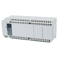
AFPXHC60R | FP-XH


|
*Photo may vary from actual product.

 This product has been confirmed that it does not contain the 6 substances specified in EU RoHS Directive 2011/65/EU and the 4 substances specified in 2015/863/EU.
| Product Number | AFPXHC60R |
| Part Number | AFPXHC60R |
| Product | FP-XH Control Unit |
| Details | C60 Power supply : 100 to 240V AC 32-point input of 24 V DC, 28-point relay output of 2 A |
| Product name | FP-XH |
As of April 20, 2024
Specifications and design of the products are subject to change without notice for the product improvement.
Spec Detail
| Item | Specifications |
|---|---|
| Product Number | AFPXHC60R |
| Part Number | AFPXHC60R |
General specifications
| Item | Specifications |
|---|---|
| Operating temperature | 0 to +55 ℃ +32 to +131 ℉ |
| Storage ambient temperature | -40 to +70 ℃ -40 to +158 ℉ |
| Operating humidity | 10 to 95 % RH (at +25 ℃ +77 ℉, non-condensing) |
| Storage ambient humidity | 10 to 95 % RH (at +25 ℃ +77 ℉, non-condensing) |
| Breakdown voltage : Relay output | AC power supply Between power supply terminal and earth terminal : 1,500 V AC for 1 minute Between power supply terminal and service power supply terminal : 1,500 V AC for 1 minute Between input terminal and earth terminal : 1,500 V AC for 1 minute Between output terminal and earth terminal : 1,500 V AC for 1 minute (Note) : Cut-off current 5 mA (Initial value at shipment) |
| Insulation resistance (Test voltage: 500 V DC) | Between power supply terminal and earth terminal : 100 MΩ or more (500 V DC using an insulation resistance meter) Between power supply terminal and service power supply terminal : 100 MΩ or more (500 V DC using an insulation resistance meter) Between input terminal and earth terminal : 100 MΩ or more (500 V DC using an insulation resistance meter) Between output terminal and earth terminal : 100 MΩ or more (500 V DC using an insulation resistance meter) |
| Vibration resistance | 5 to 8.4 Hz, 3.5 mm 0.138 in single amplitude 8.4 to 150 Hz, Acceleration 9.8 m/s2 10 min. each in the X, Y and Z directions (1 octave/min) |
| Shock resistance | 147 m/s2, 4 times each in the X, Y and Z directions |
| Noise resistance | 1,000 V [P-P] with pulse widths of 50 ns and 1 μs (using a noise simulator) (Power supply terminal) |
| Operating condition | No corrosive gas and no excessive dust |
| Applicable standard for EC directives | EMC directive: EN 61131-2 (directive concerning emission, immunity and low voltage) |
| Overvoltage class | Category II |
| Level of contamination | 2 |
Functional specifications
| Item | Specifications |
|---|---|
| Programming method | Relay symbol |
| Control method | Cyclic operation |
| Program memory | Built-in Flash ROM |
| Program capacity | 24 k / 32 k / 40 k steps (switch-over) (Note) : When changing the system register No.0 (sequence program capacity), the data register (DT) capacity will also change. |
| Basic instructions | Approx. 110 |
| High-level instructions | Approx. 220 |
| Operation speed | [Basic instruction (ST)] Approx. 0.04 μs/step (under 7 k steps) Approx. 0.7 μs/step (7 k steps or more) [High-level instruction (F0MV)] Approx. 0.22 μs/step (under 7 k steps) Approx. 1.73 μs/step (7 k steps or more) |
| Operation memory : Link relay : External input (X) | 1,760 points (X0 to X109F) (Note) : The number of points in the table is the number of points of operation memory. The number of points actually available to be used is determined by the hardware configuration. |
| Operation memory : Link relay : External output (Y) | 1,760 points (Y0 to Y109F) (Note) : The number of points in the table is the number of points of operation memory. The number of points actually available to be used is determined by the hardware configuration. |
| Operation memory : Link relay : Internal relay (R) | Default: 8,192 points (R0 to R511F) FP-X compatible specifications: 4,096 points (Note) : Can be selected by the setting of the system register No. 1 (internal relay capacity). To provide compatibility with the conventional FP-X series control unit, select 4,096 points. |
| Operation memory : Link relay : Special internal relay (R) | 240 points |
| Operation memory : Link relay : Timer / Counter (T / C) | 1,024 points (Initial settings Timer: 1,008 points, Counter: 16 points) (Note) : The number of timer points can be changed by the setting of the system register No.5. |
| Operation memory : Link relay : Link relay (L) | 2,048 points (L0 to L127F) |
| Operation memory : Memory area : Data register (DT) | 64 k, 32 k, 12 k words * DT capacity varies according to the program capacity |
| Operation memory : Memory area : Special data register (DT) | 500 words |
| Operation memory : Memory area : Link data register (LD) | 256 words (LD0 to LD255) |
| Operation memory : Memory area : File register (FL) | None |
| Operation memory : Memory area : Index register (I) | 14 words (I0 to ID) |
| Differential points | Points for program capacity |
| Master control relay points (MCR) | 256 points |
| Number of labels (JMP + LOOP) | 256 points |
| Number of step ladders | 1,000 steps |
| Number of subroutines | 500 subroutines |
| Number of interrupt program | Input 14, Constant 1 |
| High-speed counter : Control unit input | Single-phase 8 channels (10 kHz × 8) or 2-phase 4 channels (10 kHz × 4) (Note 1) : The maximum counting speed and maximum output frequency for the high-speed counter, pulse output and PWM output indicate the specifications for the voltage of 24 V DC and ambient temperature of +25 ℃ +77 ℉. The frequency may decrease depending on voltage, temperature or combination of functions used. (Note 2) : The inputs and outputs used for each function of the high-speed counter, pulse output, PWM output, pulse catch input or interrupt input cannot be allocated in duplication. |
| High-speed counter : Pulse I/O with cassette installed | Single-phase 4 channels (100 kHz × 4) or 2-phase 2 channels (50 kHz × 2) *with two cassettes installed (Note 1) : The maximum counting speed and maximum output frequency for the high-speed counter, pulse output and PWM output indicate the specifications for the voltage of 24 V DC and ambient temperature of +25 ℃ +77 ℉. The frequency may decrease depending on voltage, temperature or combination of functions used. (Note 2) : The inputs and outputs used for each function of the high-speed counter, pulse output, PWM output, pulse catch input or interrupt input cannot be allocated in duplication. |
| Pulse output / PWM output : Pulse I/O with cassette installed | 2 channels *with two cassettes installed [Pulse output] each 100 kHz [PWM output] 2 channels *with two cassettes installed 1 Hz to 70 kHz (Resolution of 1000) 70.001 kHz to 100 kHz (Resolution of 100) (Note 1) : The maximum counting speed and maximum output frequency for the high-speed counter, pulse output and PWM output indicate the specifications for the voltage of 24 V DC and ambient temperature of +25 ℃ +77 ℉. The frequency may decrease depending on voltage, temperature or combination of functions used. (Note 2) : The inputs and outputs used for each function of the high-speed counter, pulse output, PWM output, pulse catch input or interrupt input cannot be allocated in duplication. |
| Pulse catch input Interrupt input |
14 points (Control unit input: 8 points, Pulse I/O cassette : 3 points × 2) (Note) : The inputs and outputs used for each function of the high-speed counter, pulse output, PWM output, pulse catch input or interrupt input cannot be allocated in duplication. |
| Periodical interrupt | 0.1 ms to 30 sec. (Note) : The inputs and outputs used for each function of the high-speed counter, pulse output, PWM output, pulse catch input or interrupt input cannot be allocated in duplication. |
| Potentiometer input | 1 channel (0 to 4,000) |
| Input time constant processing | Available |
| Clock / calendar | Available (only when the master memory cassette AFPX-MRTC and battery are installed) |
| Flash ROM backup : Backup by F12 / P13 instructions | All area of Data register |
| Flash ROM backup : Automatic backup when power is off | Counter: 16 points, Internal relay: 128 points, Data register: 315 words |
| Battery backup | Memory set in hold area of system register (only when battery is installed) |
| Battery lifetime | 5 years or more in the actual use condition (operating 8 hours a day) (Note) : Battery lifetime values is calculated when the power is not completely turned on. Since the actual value depends on conditions of use, in practice, the lifetime may be shorter. |
| Password | Yes (Can be selected from 4 digits, 8 digits or 32 digits) |
| Self-diagnostic function | Watchdog timer, program syntax check, etc. |
| PLC link function | Max. 16 units, link relay: 1,024 points, link register: 128 words (Data transfer, remote programming: Not available) |
| Rewriting in RUN mode | Available (downloading in RUN mode, program rewriting in RUN mode) (Max. 512 steps) |
Accessories (Option)

|
| Product Number | AFPABAT001 |
| Part Number | AFPABAT001 |
| Product name | Backup battery |
BY EMAIL
- U.S.A.
- +1-800-344-2112
- Europe
- +49-89-45354-1000
- China
- +86-10-59255988
- Singapore
- +65-6299-9181


Requests to customers (Automation Control Components & Industrial Device) [Excluding specific product]
Requests to customers (Automation Control Components & Industrial Device) [For specific product]
Requests to customers (FA Sensors & Components [Excluding motors])
Requests to customers (Dedicated to industrial motors)
- COMPONENTS & DEVICES
- FA SENSORS & COMPONENTS
- Fiber Sensors
- Photoelectric Sensors / Laser Sensors
- Micro Photoelectric Sensors
- Light Curtains / Safety Components
- Area Sensors
- Inductive Proximity Sensors
- Particular Use Sensors
- Sensor Options
- Wire-Saving Systems
- Programmable Controllers / Interface Terminal
- Human Machine Interface
- Pressure Sensors / Flow Sensors
- Measurement Sensors
- Static Control Devices
- Laser Markers / 2D Code Readers
- Machine Vision System
- Energy Management Solutions
- Timers / Counters / FA Components
- MOTORS
![]()