
 Business
> Industrial Devices
> Automation Controls Top
> Motors for FA & Industrial Application
> Motor
> AC Servo Motors
> MINAS A6 Family Servo Motor
> Lineup
> MDMF102L1C6
Business
> Industrial Devices
> Automation Controls Top
> Motors for FA & Industrial Application
> Motor
> AC Servo Motors
> MINAS A6 Family Servo Motor
> Lineup
> MDMF102L1C6
![]()
Automation Controls Datasheet
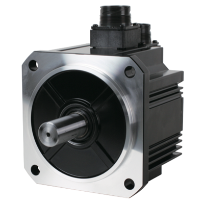
MDMF102L1C6 | MINAS A6 Family Servo Motor


Email the information about MDMF102L1C6 | MINAS A6 Family Servo Motor to whom you indicate.
Your email has been sent.

| Part Number | MDMF102L1C6 |
| Product | Servo Motor |
| Details | Middle inertia, Connector type |
| Product name | MINAS A6 Family Servo Motor |
| Features | 50 W to 22 kW, Input power supply for Driver: Voltage DC 24 V/48 V・AC 100 V/200 V/400 V, 23 bit Absolute/Incremental・battery-less Absolute/Incremental encoder, Frequency response 3.2 kHz |
As of April 18, 2024
Specifications and design of the products are subject to change without notice for the product improvement.
Spec Detail
| Item | Specifications |
|---|---|
| Part Number | MDMF102L1C6 |
| Details | Middle inertia, Connector type |
| Family Name | MINAS A6 |
| Series | MDMF Series |
| Type | Middle inertia |
| Protection class | IP67 |
| About Enclosure | Except rotating portion of output shaft and connecting pin part of the motor connector and the encoder connector. |
| Environmental Conditions | For more details, please refer to the instruction manual. |
| Flange sq. dimension | 130 mm sq. |
| Flange sq. dimension (Unit:mm) | 130 |
| Motor lead-out configuration | Connector |
| Motor encoder connector | Motor connector: JL10, Encoder connector: Large size JL10 |
| About Motor encoder connector | Connector JL10 (Large size): Also applicable to screwed type |
| Power supply capacity (kVA) | 2.4 |
| Voltage specifications (V) | 200 |
| Rated output (W) | 1000 |
| Rated current (A (rms)) | 5.2 |
| Holding brake | without |
| Mass (kg) | 4.6 |
| Oil seal | with |
| Shaft | Round |
| Rated torque (N ⋅ m) | 4.77 |
| Continuous stall torque (N ⋅ m) | 5.25 |
| Momentary Max. peak torque (N ⋅ m) | 14.3 |
| Max. current (A (o-p)) | 22 |
| Regenerative brake frequency (times/min) | Without option :No limit With option :No limit Option (External regenerative resistor) Part No. : DV0P4284 |
| About regenerative brake frequency | Please refer to the details of [Motor Specification Description] , Note: 1, and 2. |
| Rated rotational speed (r/min) | 2000 |
| Rated rotational Max. speed (r/min) | 3000 |
| Moment of inertia of rotor ( x10-4 kg ⋅ m²) | 6.18 |
| Recommended moment of inertia ratio of the load and the rotor | 10 times or less |
| About recommended moment of inertia ratio of the load and the rotor | Please refer to the details of [Motor Specification Description] ,Note: 3. |
| Rotary encoder: specifications | 23-bit Absolute/Incremental system |
| Notice | When using a rotary encoder as an incremental system (not using multi-turn data), do not connect a battery for absolute encoder. |
| Rotary encoder: Resolution | 8388608 |
Permissible load
| Item | Specifications |
|---|---|
| During assembly: Radial load P-direction (N) | 980 |
| During assembly: Thrust load A-direction (N) | 588 |
| During assembly: Thrust load B-direction (N) | 686 |
| During operation: Radial load P-direction (N) | 490 |
| During operation: Thrust load A, B-direction (N) | 196 |
| About permissible load | For details, refer to the [Motor Specification Description] "Permissible Load at Output Shaft". |
As of April 18, 2024
Specifications and design of the products are subject to change without notice for the product improvement.
Applicable Driver
| Part Number | Series | Type | I/F Classification of type | Frame | Supply voltage |
|---|---|---|---|---|---|
| MDDLN45NE | A6NE series | RTEX, Ultra high-speed Network (Basic type) | RTEX | D-Frame | Single/3-phase 200 V |
| MDDLN45SE | A6SE series | Position control type | Pulse train only | D-Frame | Single/3-phase 200 V |
| MDDLN45SG | A6SG series | RS485/RS232 Communication type | Pulse, Modbus (RS485 /RS232) | D-Frame | Single/3-phase 200 V |
| MDDLT45NF | A6NF series | RTEX, Ultra high-speed Network type (Multi type) | RTEX | D-Frame | Single/3-phase 200 V |
| MDDLT45SF | A6SF series | Multifunction type | Analog /Pulse, Modbus (RS485 /RS232) | D-Frame | Single/3-phase 200 V |
As of April 18, 2024
Specifications and design of the products are subject to change without notice for the product improvement.
Torque charactristics
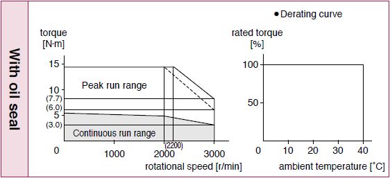
Dotted line represents the torque at 10 % less supply voltage.
As of April 18, 2024
Specifications and design of the products are subject to change without notice for the product improvement.
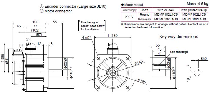
[Unit:mm]
Dimensions
BY EMAIL
- U.S.A.
- +1-800-344-2112
- Europe
- +49-89-45354-1000
- China
- +86-10-59255988
- Singapore
- +65-6299-9181


Requests to customers (Automation Control Components & Industrial Device) [Excluding specific product]
Requests to customers (Automation Control Components & Industrial Device) [For specific product]
Requests to customers (FA Sensors & Components [Excluding motors])
Requests to customers (Dedicated to industrial motors)
- COMPONENTS & DEVICES
- FA SENSORS & COMPONENTS
- Fiber Sensors
- Photoelectric Sensors / Laser Sensors
- Micro Photoelectric Sensors
- Light Curtains / Safety Components
- Area Sensors
- Inductive Proximity Sensors
- Particular Use Sensors
- Sensor Options
- Wire-Saving Systems
- Programmable Controllers / Interface Terminal
- Human Machine Interface
- Pressure Sensors / Flow Sensors
- Measurement Sensors
- Static Control Devices
- Laser Markers / 2D Code Readers
- Machine Vision System
- Energy Management Solutions
- Timers / Counters / FA Components
- MOTORS
![]()
Before Purchasing and Using the Products (Motors for FA & Industrial Application)
Specifications and design of the products displayed on this website are subject to change without notice for the product improvement. (including specification change, manufacturing location change, End Of Sales, End Of Life). Therefore, be sure to request and confirm in advance the most current specifications, which explain the specifications in detail, before the final stage of your design, purchasing or use for any application.
Safety Precautions
• Important Notes on exporting this product or equipment containing this product;
If the end-user or application of this product is related to military affairs or weapons, its export may be controlled by “Foreign Exchange and Foreign Trade Control Law” of Japan where export license will be required before product can be exported from Japan.
• This product is designed and manufactured for use in General Purpose Industrial Equipment and it is not intended to be used in equipment or system that may cause personal injury or death.
• All servicing such as installation, wiring, operation, maintenance and etc., should be performed by qualified personnel only.
• Tighten mounting screws with an adequate torque by taking into consideration strength of the screws and the characteristics of material to which the product will be mounted. Over tightening can damage the screw and/or material; under tightening can result in loosening.
*Example: apply 2.7 N·m – 3.3 N·m torque when tightening steel screw (M5) to steel surface.
• Install safety equipment to prevent serious accidents or loss that is expected in case of failure of this product.
• Consult us before using this product under such special conditions and environments as nuclear energy control, aerospace, transportation, medical equipment, various safety equipments or equipments which require a lesser air contamination.
• We have been making the best effort to ensure the highest quality of our products, however, some applications with exceptionally large external noise disturbance and static electricity, or failure in input power, wiring and components may result in unexpected action. It is highly recommended that you make a fail-safe design and secure the safety in the operative range.
• If the motor shaft is not electrically grounded, it may cause an electrolytic corrosion to the bearing, depending on the condition of the machine and its mounting environment, and may result in the bearing noise. Checking and verification by customer is required.
• Failure of this product depending on its content may generate smoke of about one cigarette. Take this into consideration when the application of the machine is clean room related.
• Please be careful when using the product in an environment with high concentrations of sulfur or sulfuric gases, as sulfuration can lead to disconnection from the chip resistor or a poor contact connection.
• Do not input a supply voltage which significantly exceeds the rated range to the power supply of this product. Failure to heed this caution may lead to damage of the internal parts, causing smoke and/or fire and other troubles.
• The user is responsible for matching between machine and components in terms of configuration, dimensions, life expectancy, characteristics, when installing the machine or changing specification of the machine. The user is also responsible for complying with applicable laws and regulations.
• Manufacturer’s warranty will be invalid if the product has been used outside its stated specifications.
• Component parts are subject to minor change to improve performance.
• Read and observe the instruction manual to ensure correct use of the product.
Warranty period
The warranty period is one year from the date of purchase or 18 months from the month of manufacture in our plant.
Warranty information
•Should any defect develop during warranty period under standard service conditions as described in the manual, the company agrees to make repairs free of charge.
Even during warranty period, the company makes fee-based repair on product containing:
| [1] | Failure or damage due to misuse, improper repair or alteration. |
|---|---|
| [2] | Failure or damage due to falling, or damage during transportation, after the original delivery |
| [3] | Defects resulting from neglect of the specification in use of the product. |
| [4] | Failure or damage due to unregulated voltage and fire, and act of natural disasters such as earthquake, lightning, wind, flood and salt pollution. |
| [5] | Defects resulting from invasion of foreign materials such as water, oil and metal pieces. Parts exceeding their standard lifetime specified in this document are excluded. |
•The company shall not be liable for any indirect, incidental or consequential damage or loss of any nature that may arise in connection with the product