【Notification of Manufacturer Change for Panasonic Industrial Devices SUNX Products and Panasonic Industrial Devices SUNX Tatsuno Products】
From April 1, 2024, the terms "Panasonic Industrial Devices SUNX Co., Ltd." and "Panasonic Industrial Devices SUNX Tatsuno Co., Ltd."
in this page and in the manuals and other documents to be downloaded will all be replaced with "Panasonic Industry Co., Ltd." and applied accordingly.
Precautions for prorer use - Inductive Proximity Sensors
|
|
Precautions for
prorer use |
|
Precautions for prorer use
Setting distance
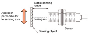
Approach perpendicular to sensing axis
|
Normally the sensor is used with the sensing object approaching from a direction perpendicular to the sensing axis. Adjust the distance to the sensing object to be within the stable sensing range which is slightly less than the maximum operation distance.
|
|
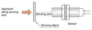
Approach along sensing axis
|
When the sensing object approaches the sensor along the sensing axis, it is detected at the maximum operation distance.
However, make sure to avoid any collision between the sensing object and the sensor, which may occur due to the sensing object speed.
|
|
Return to top
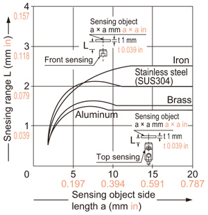
Type of metal objects and sensing range
The sensing range is specified for the standard sensing object. If the sensing object is smaller, or is non-ferrous, the sensing range shortens.
Correlation between sensing object size and sensing range (In case of GXL-8 type)
Correction coefficient for different sensing object materials (In case of GXL-8 type)
| Sensing object |
Correction coefficient |
| Iron |
1 |
| Stainless steel (SUS304) |
0.82 approx. |
| Brass |
0.59 approx. |
| Aluminum |
0.57 approx. |
| Note : | The sensing range also changes if the sensing object is plated. |
|---|
Return to top
Mounting
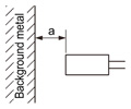
Influence of surrounding metal
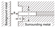
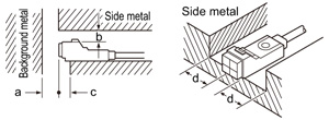
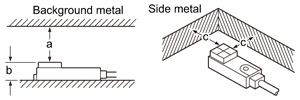
Surrounding metal may affect the performance of the inductive proximity sensor. Keep the specified distance between the surrounding metal and the sensor.
(For details, refer to the section "PRECAUTIONS FOR PROPER USE" of each sensor.)
<Cylindrical type and threaded (shielded) type>
Beware of background metal
|
<Threaded (non-shielded) type>
Beware of background and surrounding metal
|
<Top sensing (non-shielded) type>
Beware of background and side metal
|
<Front sensing (non-shielded) type>
Beware of background and side metal
|
Mutual interference
When several inductive proximity sensors are mounted close together, the high frequency magnetic field emanating from one sensor exerts an electromagnetic influence on the other sensors, mutually causing their operation to become unstable (called mutual interference). In this case, the following countermeasures are necessary.
Countermeasures(1): Keep sufficient spacing.
Face to face mounting |
 |
|
Parallel mounting |
 |
|
(For details, refer to the section "PRECAUTIONS FOR PROPER USE" of each sensor.)
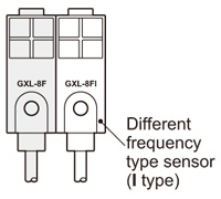
Countermeasures(2):
When used along with a different frequency type (I type), in which the oscillation frequency is different, two sensors can be parallely mounted next to each other.
Return to top
Bleeder resistance setting procedures
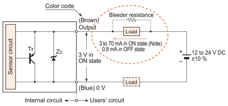
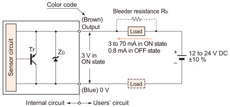
The DC 2-wire type inductive proximity sensors manufactured by Panasonic Industrial Devices SUNX do not normally function in the case where the load current is under 3 mA when the load is connected to the output. In that case, it is necessary for a load current of 3 mA or more to flow by connecting the load to the resistance in parallel. This resistance is called "bleeder resistance".
The I/O circuit diagram of the DC 2-wire type inductive proximity sensors is described as below.
I/O circuit of DC-2 wire type
Symbols
| ZD |
: |
Surge absorption zener diode |
| Tr |
: |
PNP output transistor |
| Note : | The maximum load current varies depending on the ambient temperature. |
|---|
|
Conditions for the load
| (1) | The load should not be actuated by the leakage current (0.8 mA) in the OFF state. |
| (2) | The load should be actuated by (supply voltage -3 V) in the ON state. |
| (3) | The current in the ON state should be between 3 to 70 mA DC. |
| In case the current is less than 3 mA, connect a bleeder resistance in parallel to the load so that a current of 3 mA, or more, flows. |
|
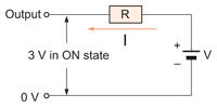
Examine the necessity for bleeder resistance
First, examine if bleeder resistance is necessary when connecting the load to the output.
|
|
Provided that
load is "R",
load current is "I",
supply voltage is "V", and output
residual voltage is 3 V,
|
you can calculate the load current "I" when output is in the ON state using the following formula.
The DC 2-wire type inductive proximity sensors manufactured by Panasonic Industrial Devices SUNX do not need bleeder resistance when I ≥ 3 mA, but need it when I < 3 mA.
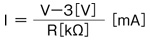
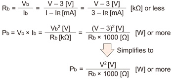
Calculation method of the necessary bleeder resistance
|
|
Provided that bleeder resistance is "Rb",
electric current flowing to "Rb" is "Ib",
voltage within Rb is "Vb",
electric current flowing to R is "IR",
load current to the sensor is "I",
and supply voltage is "V";
| I |
= |
IR + Ib = 3[mA] or more |
| Vb |
= |
Rb × Ib = R × IR |
| |
= |
V - 3[V] |
the relational expression above is formulated.
|
The bleeder resistance Rb and bleeder resistance power Pb can be calculated using the formula below.
| * | In actuality, select a wattage that is a few times greater than Pb. |
|---|
Bleeder resistance that is necessary for the DC 2-wire type
<In the case that load current is under 3 mA when the output is in the ON state>
The bleeder resistance Rb and bleeder resistance power Pb can be calculated using the formula below.
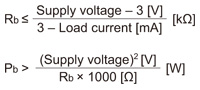
| * | In actuality, select a wattage that is a few times greater than Pb. |
|
Return to top
Other precautions
- Our products have been developed / produced for industrial use only.
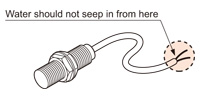
- Although the protection degree is specified for the sensor including the cable, the cable end is not waterproof and is not covered by the protection specified. Hence, make sure that water does not seep in from the cable end.
- Make sure that the power supply is off while wiring.
- Verify that the supply voltage variation is within the rating.
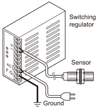
- If power is supplied from a commercial switching regulator, ensure that the frame ground (F.G.) terminal of the power supply is connected to an actual ground.
- If using electromagnetic valves, magnet switches, motors, etc. simultaneously in your system, control surges with a surge killer. Not doing so will cause chattering and other malfunctions.
- In case noise generating equipment (switching regulator, inverter motor, etc.) is used in the vicinity of this product, connect the frame ground (F.G.) terminal of the equipment to an actual ground.
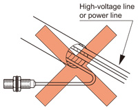
- Do not run the wires together with high-voltage lines or power lines or put them in the same raceway. This can cause malfunction due to induction.
- Using wireless devices around sensors and wires may cause a malfunction. So make sure not to approach those.
- Take care that the sensor does not come in direct contact with organic solvents, such as, thinner, etc.
- Make sure that the sensing end is not covered with metal dust, scrap or spatter. It will result in malfunction.
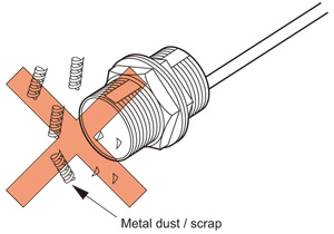
(The spatter-resistant type GX-F□U-J, GH-F8SE prevents sticking of spatter due to its fluorine resin coating.)
- These sensors are only for indoor use.
- Make sure that stress by forcible bend or pulling is not applied directly to the sensor cable joint.
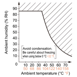
- The usage environment should be within the ranges described in the specifications.
Use sensors within the range shown in the white part of the ambient temperature / humidity graph below and also within the certified ambient temperature and humidity range of each product. When using sensors within the range shown in the diagonal line shaded part of the graph, there is a possibility that condensation may occur depending on changes in the ambient temperature.
Please be careful not to let this happen.
Furthermore, pay attention that freezing does not occur when using below 0℃ +32℉. Please avoid condensation and freezing when storing the product as well.
Return to top
Related Products
Download
- proximity_e.pdf

Return to top
|
|
Precautions for
prorer use |
|
Return to top

 Business
> Industrial Devices
> Automation Controls Top
> Service & Support
> FA Technical Support
> Technical Guide (FA Sensors)
> Inductive Proximity Sensors
> Precautions for prorer use
Business
> Industrial Devices
> Automation Controls Top
> Service & Support
> FA Technical Support
> Technical Guide (FA Sensors)
> Inductive Proximity Sensors
> Precautions for prorer use