[Notification of CAD Data Download Issue]
We regret to inform you that we are currently experiencing issues with downloading CAD data for some products.
We are investigating the cause of this problem. We apologize for any inconvenience this may cause and appreciate your understanding.

 Business
> Industrial Devices
> Automation Controls Top
> Components & Devices
> Connectors
> Automotive Connectors
> CW1
> Rating/Performance
Business
> Industrial Devices
> Automation Controls Top
> Components & Devices
> Connectors
> Automotive Connectors
> CW1
> Rating/Performance
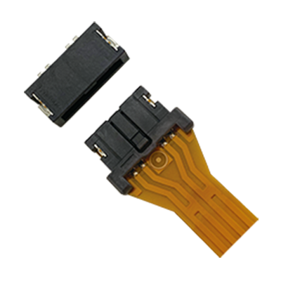
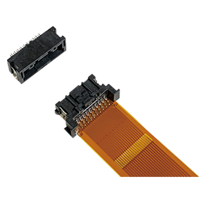
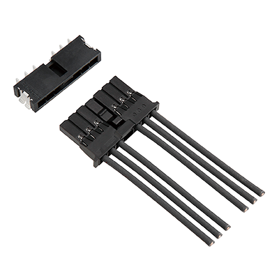
CW1
For Automotive Application with 125°C heat resistance 3.4mm low profile design.


Features
- ●
3.4 mm low profile design.
- ●
Suitable for automotive applications that require vibration and heat resistance (125℃) characteristics.
- ●
“Anti-misoperation bridge structure” prevents unintended operation of mating lock.
Applications
- ●
LED module connection in automotive head lamps
|
Characteristics
| Item | Specifications | Conditions | |
|---|---|---|---|
| Electrical characteristics |
Rated current | Each pin: 3.0 A | Maximum current can be applied to one contact. (Except for the capacity of wire.) |
| Rated voltage | 50 V DC | ||
| Dielectric strength | 1,000 V AC for 1 min | Detection current: 1 mA (No short or damage) | |
| Insulation resistance | Min. 100 MΩ | Using 500 V DC megger (1 min) | |
| Contact resistance | Max. 10 mΩ (Initial) Max. 20 mΩ (after test) |
Except wire conductor resistance. Measured at DC 10 mA |
|
| Mechanical characteristics |
Insertion force | Max. 13.0 N (Initial stage・2 pins) Max. 18.0 N (Initial stage・4 pins) Max. 23.0 N (Initial stage・6 pins) Max. 28.0 N (Initial stage・8 pins) |
|
| Removal force | Max. 13.0 N (Initial stage・2 pins) Max. 18.0 N (Initial stage・4 pins) Max. 23.0 N (Initial stage・6 pins) Max. 28.0 N (Initial stage・8 pins) |
Measured by removal of housing lock. | |
| Housing lock force | Min. 30 N (Initial stage) | ||
| Environmental characteristics |
Temperature and humidity of ambient, storage and transportation | –40 to +125°C (Including temperature rise when applying current) (Storage and transportation temperature is –40 to +50°C in a packing state.)*1 |
No icing. No condensation |
| Soldering heat resistance | The initial specification must be satisfied electrically and mechanically | Max. peak temperature of 260°C Reflow soldering: Max. 2 times (PC board surface temperature near the receptacle) Soldering iron: 300°C within 5 sec., 350°C within 3 sec. |
|
| Thermal shock resistance (Receptacle and plug mated) | After 500 cycles Contact resistance: Max. 20 mΩ |
 *Vapor phase |
|
| Humidity resistance (Receptacle and plug mated) |
After 96 hours Contact resistance: Max. 20 mΩ Insulation resistance: Min. 100 MΩ |
Bath temperature 60 ±2°C Humidity 90 % RH |
|
| Heat resistance (Receptacle and plug mated) | After 120 hours Contact resistance: Max. 20 mΩ |
Bath temperature 125 ±2°C | |
| Vibration resistance (Receptacle and plug mated) |
Current shut off should not exceed 1 µs during vibration test. (Contact resistance: Max. 20 mΩ) |
Acceleration: 44.0 m/s² |
|
| Shock resistance (Receptacle and plug mated) |
Current shut off should not exceed 1 µs during shock test. |
Acceleration: 981 m/s² Operation time: 6 ms Testing tool: Refer to Fig.1 *2 Direction: 6 direction (±X, ±Y, ±Z) (Different samples are used for each direction.) Number: 3 times Detection current: 10 mA |
|
| Lifetime characteristics |
Insertion and removal life | 30 times (Contact resistance: Max. 20 mΩ) | Speed: 25 mm/min |
| Solder paste thickness | The initial specification must be satisfied electrically and mechanically | Recommendation t=0.15 mm | |
| *1. As the humidity range differs depending on the ambient temperature, the humidity range indicated below should be used. This temperature and humidity range does not guarantee permanent performance. |
 |
| *2. Fig. 1 |
 |
Material and surface treatment
Receptacle
| Name | Material | Color | Surface treatment |
|---|---|---|---|
| Body | LCP (UL94 V-0) | Black | - |
| Post | Copper Alloy | - | Contact portion: PdNi + Au flash plating over nickel Soldering portion: Sn plating over nickel |
| Metal tab | Copper Alloy | - | Soldering portion: Sn plating over nickel |
Housing
| Name | Material | Color | Surface treatment |
|---|---|---|---|
| Housing | PBT (UL94 HB) | Black | - |
Contact
| Name | Material | Color | Plating |
|---|---|---|---|
| Contact | Copper alloy | - | Contact portion: PdNi + Au flash plating over nickel Barrel portion: Sn plating over nickel |
Applicable wires
| Wire range | Wire specifications | ||
|---|---|---|---|
| Number of strands/Strand diameter(pcs/mm) | Conductor sectional area(mm²) | Insulation diameter(mm) | |
| AWG #24 | 11/0.16 | 0.2210 | φ1.22 to φ1.52 |
| AWG #22 | 17/0.16 | 0.3416 | |
| AVSS0.3 | 7/0.26 | 0.3715 | |
| Tinned annealed copper wire Furukawa Electric Co., Ltd. BEAMEX ER500 |
12/0.18 | 0.3 | φ1.52 |
|
Related Information
BY EMAIL


Requests to customers (Automation Control Components & Industrial Device) [Excluding specific product]
Requests to customers (Automation Control Components & Industrial Device) [For specific product]
Requests to customers (FA Sensors & Components [Excluding motors])
Requests to customers (Dedicated to industrial motors)
- COMPONENTS & DEVICES
- FA SENSORS & COMPONENTS
- Fiber Sensors
- Photoelectric Sensors / Laser Sensors
- Micro Photoelectric Sensors
- Light Curtains / Safety Components
- Area Sensors
- Inductive Proximity Sensors
- Particular Use Sensors
- Sensor Options
- Wire-Saving Systems
- Programmable Controllers / Interface Terminal
- Human Machine Interface
- Pressure Sensors / Flow Sensors
- Measurement Sensors
- Static Control Devices
- Laser Markers / 2D Code Readers
- Machine Vision System
- Energy Management Solutions
- Timers / Counters / FA Components
- MOTORS
![]()