
 Business
> Industrial Devices
> Automation Controls Top
> Components & Devices
> Relays / Couplers
> High-capacity DC Cutoff Relay
> EP Relays
> Rating/Performance
Business
> Industrial Devices
> Automation Controls Top
> Components & Devices
> Relays / Couplers
> High-capacity DC Cutoff Relay
> EP Relays
> Rating/Performance
EP Relays
-
Lineup
-
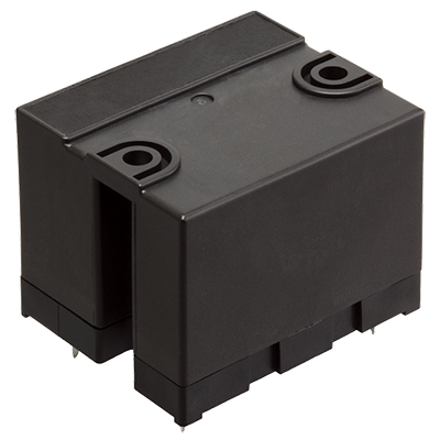
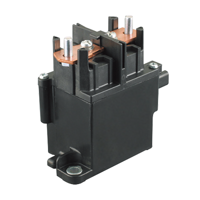 EP Relays
High capacity of Max. 1,000 V DC Cut-off possible
EP Relays
High capacity of Max. 1,000 V DC Cut-off possible
-
 HE-V Relays
Max. 1,000 V DC, 20 A cut-off possible, High capacity DC power relays
HE-V Relays
Max. 1,000 V DC, 20 A cut-off possible, High capacity DC power relays
-
- CAD data Catalogs/Datasheets
- FAQ
|
Partly to Be Discontinued
|
|
Coil data
- Operating characteristics such as "Operate voltage" and "Release voltage" are influenced by mounting conditions, ambient temperature, etc.
Therefore, please use the relay within ±5% of rated coil voltage. - "Initial" means the condition of products at the time of delivery.
| Type | Rated coil voltage |
Operate voltage * (at 20°C) |
Release voltage * (at 20°C) |
Rated operating current (±10%, at 20°C) |
Coil resistance (±10%, at 20°C) |
Rated operating power |
Max. allowable voltage |
|---|---|---|---|---|---|---|---|
| 20 A | 12 V DC | Max. 75% V of Rated coil voltage (Initial) |
Min. 4.17% V of Rated coil voltage (Initial) |
327 mA | 36.7 Ω | 3.9 W | 133% V of rated coil voltage |
| 24 V DC | 163 mA | 146.8 Ω | |||||
| 80 A | 12 V DC | Min. 8.3% V of Rated coil voltage (Initial) |
353 mA | 34 Ω | 4.2 W | ||
| 24 V DC | 176 mA | 136 Ω |
* square, pulse driver
Note) When using a DC power supply, use one that provides a current capacity leeway of at least 150% of the rated operating current.
Specifications
| Item | Specifications | ||
|---|---|---|---|
| 20 A type | 80 A type | ||
| Contact data |
Contact arrangement | 1 Form A | |
| Contact material | Copper alloy | Tungsten type and Copper alloy |
|
| Contact rating (resistive) |
20 A 400 V DC | 80 A 400 V DC | |
| Max. switching power (resistive) |
20,000 W | 80,000 W | |
| Max. switching voltage | 1,000 V DC | ||
| Max. cut-off current | - | 800 A 300 V DC (1 cycle) *3 |
|
| Overload cut-off | 60 A 400 V DC (Min. 50 cycles) *3 | 120 A 400 V DC (Min. 50 cycles) *3 | |
| Reverse cut-off | -20 A 200 V DC (Min. 100 cycles) *3 | -80 A 200 V DC (Min. 1,000 cycles) *3 | |
| Max. switching current | 20 A DC continuity (3 mm2 Wire) 40 A DC 10 min (3 mm2 Wire) 60 A DC 1 min (3 mm2 Wire) |
80 A DC continuity (15 mm2 Wire) 120 A DC 15 min (15 mm2 Wire) 180 A DC 2 min (15 mm2 Wire) |
|
| Min. switching load (reference value) *1 |
1 A 12 V DC | 1 A 12 V DC | |
| Contact voltage drop (Initial) |
Max. 0.2 V (When carrying current is 20 A) |
Max. 0.067 V (When carrying current is 20 A) |
|
| Insulation resistance (initial) | Min. 100 MΩ (at 500 V DC, Measured portion is the same as the case of dielectric strength.) |
||
| Dielectric strength (initial) |
Between open contacts |
2,500 Vrms for 1 min (detection current: 10 mA) | |
| Between contact and coil |
2,500 Vrms for 1 min (detection current: 10 mA) | ||
| Coil holding voltage *4 | - | 50 to 100% V (at 80°C) | |
| Time characteristic (initial) |
Operate time | Max. 50 ms at rated coil voltage (at 20°C, without bounce) | |
| Release time | Max. 30 ms at rated coil voltage (at 20°C, without bounce, without diode) | ||
| Shock resistance |
Functional | For ON: 196 m/s2 (half-sine shock pulse: 11 ms, detection time: 10 µs) For OFF: 98 m/s2 (half-sine shock pulse: 11 ms, detection time: 10 µs) |
|
| Destructive | 490 m/s2 (half-sine shock pulse: 6 ms) | ||
| Vibration resistance |
Functional | 10 to 200 Hz acceleration 43 m/s2 constant (detection time: 10 µs) | |
| Destructive | 10 to 200 Hz acceleration 43 m/s2 constant (3 directions, each 4 hours) | ||
| Expected life | Mechanical life | Min. 200 x 103 ope. | |
| Conditions | Conditions for usage, transport and storage *2 |
Ambient temperature: -40 to +80°C (storage: Max. +85°C), Humidity: 5 to 85% RH (Avoid icing and condensation) |
|
| Unit weight | Approx. 180 g | Approx. 400 g | |
| *1 | This value can change due to the switching frequency, environmental conditions, and desired reliability level, therefore it is recommended to check this with the actual load. |
|---|---|
| *2 | The upper limit of the ambient temperature is the maximum temperature that can satisfy the coil temperature rise value. Refer to Usage, transport and storage conditions in NOTES. |
| *3 | Conditions: Varistor used for coil surge absorption. Note) if a diode is used the life will be lower. |
| *4 | Coil holding voltage is the coil voltage after 100 ms from the applied rated coil voltage. |
Expected electrical life *1
Conditions: Resistive load
| Type | Switching capacity | Number of operations |
|---|---|---|
| 20 A | 10 A 1,000 V DC | Min. 103 ope. (switching frequency: 6 times/min) *2 |
| 20 A 400 V DC | Min. 3 x 10³ ope. (switching frequency: 6 times/min) *2 | |
| 80 A | 80 A 400 V DC | Min. 103 ope. (switching frequency: 20 times/min) *2 |
| *1 | Please refer to the reference data for switching and cut-off at 400 V DC and higher. |
|---|---|
| *2 | Conditions: Varistor used for coil surge absorption. Note) if a diode is used the life will be lower. |
|
Related Information
CONTACT US
If you have any questions, please select the option below to contact us or find answers.
CONTACT US
BY EMAIL
BY EMAIL
Please click your area to select country or region


Related Information
Service & Support
Requests to customers (Automation Control Components & Industrial Device) [Excluding specific product]
Requests to customers (Automation Control Components & Industrial Device) [For specific product]
Requests to customers (FA Sensors & Components [Excluding motors])
Requests to customers (Dedicated to industrial motors)
- COMPONENTS & DEVICES
- FA SENSORS & COMPONENTS
- Fiber Sensors
- Photoelectric Sensors / Laser Sensors
- Micro Photoelectric Sensors
- Light Curtains / Safety Components
- Area Sensors
- Inductive Proximity Sensors
- Particular Use Sensors
- Sensor Options
- Wire-Saving Systems
- Programmable Controllers / Interface Terminal
- Human Machine Interface
- Pressure Sensors / Flow Sensors
- Measurement Sensors
- Static Control Devices
- Laser Markers / 2D Code Readers
- Machine Vision System
- Energy Management Solutions
- Timers / Counters / FA Components
- MOTORS
![]()