
 Business
> Industrial Devices
> Automation Controls Top
> Components & Devices
> Relays / Couplers
> Power Relays (Over 2A)
> Power Relays (Over 2A) Lineup
> LQ Relays
> Rating/Performance
Business
> Industrial Devices
> Automation Controls Top
> Components & Devices
> Relays / Couplers
> Power Relays (Over 2A)
> Power Relays (Over 2A) Lineup
> LQ Relays
> Rating/Performance
LQ Relays
-
Lineup
-
 DE Relays
Compliant with European safety standards, 1 Form A/2 Form A/1 Form A 1 Form B 10 A/8 A Polarized power relays
DE Relays
Compliant with European safety standards, 1 Form A/2 Form A/1 Form A 1 Form B 10 A/8 A Polarized power relays
-
 DJ Relays
High insulation, 1-pole/2-pole 16 A, Polarized power relays
DJ Relays
High insulation, 1-pole/2-pole 16 A, Polarized power relays
-
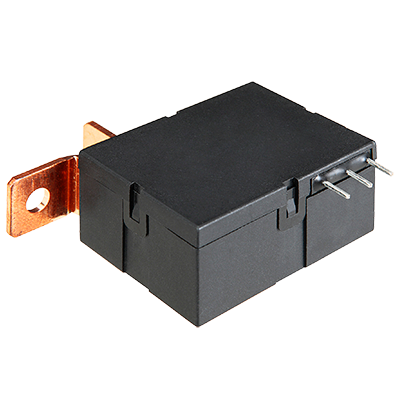
 DJ-H Relays
Suitable for lighting and motor load, 1 Form A 50 A, Latching relays
DJ-H Relays
Suitable for lighting and motor load, 1 Form A 50 A, Latching relays
-
 DK Relays
1 Form A 10 A, 1 Form A 1 Form B/2 Form A 8 A, Small polarized power relays
DK Relays
1 Form A 10 A, 1 Form A 1 Form B/2 Form A 8 A, Small polarized power relays
-
 DS Power Relays
1 Form A 8 A (AC) / 5 A (DC) , 1 Form A 1 Form B/2 Form A 5 A (AC/DC) , Small polarized power relays
DS Power Relays
1 Form A 8 A (AC) / 5 A (DC) , 1 Form A 1 Form B/2 Form A 5 A (AC/DC) , Small polarized power relays
-
 DW Relays
1 Form A 8 A/16 A, Small, Polarized power relays (latching type)
DW Relays
1 Form A 8 A/16 A, Small, Polarized power relays (latching type)
-
 DY Relays
1 Form A 10 A, 1 Form A 1 Form B 8 A, Small polarized power relays
DY Relays
1 Form A 10 A, 1 Form A 1 Form B 8 A, Small polarized power relays
-
 DZ-S Relays
IEC62055-31 UC3 compliant, 1 Form A 90 A, Power latching relays
DZ-S Relays
IEC62055-31 UC3 compliant, 1 Form A 90 A, Power latching relays
-
 HE Relays
TV-10/TV-15 rated, 1 Form A 30 A, 2 Form A 25 A, Power relays
HE Relays
TV-10/TV-15 rated, 1 Form A 30 A, 2 Form A 25 A, Power relays
-
 HE Relays PV Type
Compact size, 1 Form A 35 A/48 A/90 A Power relays for solar inverter
HE Relays PV Type
Compact size, 1 Form A 35 A/48 A/90 A Power relays for solar inverter
-
 HE-N Relays
High capacity 120 A 490 V AC 1 Form A power relay
HE-N Relays
High capacity 120 A 490 V AC 1 Form A power relay
-
 HE-S Relays
Compact size 2a and 2a1b 40 A power relays for energy management and industrial equipment
HE-S Relays
Compact size 2a and 2a1b 40 A power relays for energy management and industrial equipment
-
 HE-R Relays
Compact size 2 Form A and 2 Form A 1Form B 80 A/4 Form A and 4 Form A and 1 Form B 40 A power relays
HE-R Relays
Compact size 2 Form A and 2 Form A 1Form B 80 A/4 Form A and 4 Form A and 1 Form B 40 A power relays
-
 JV-N Relays
1 Form A 16 A, low profile: 10.9 mm power relays for heater control
JV-N Relays
1 Form A 16 A, low profile: 10.9 mm power relays for heater control
-
 JW Relays
1 Form A/1 Form C/2 Form A/2 Form C, 5 A/10 A, Power relays
JW Relays
1 Form A/1 Form C/2 Form A/2 Form C, 5 A/10 A, Power relays
-
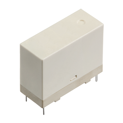
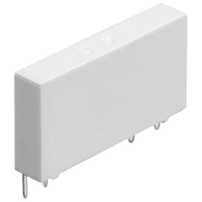
 LD-P Relays
Compliant with IEC/EN60335-1/ EN60079-15 (VDE approved) 1 Form A 5 A Slim power relays
LD-P Relays
Compliant with IEC/EN60335-1/ EN60079-15 (VDE approved) 1 Form A 5 A Slim power relays
-
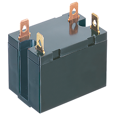
 LF Relays
Ideal for compressor and inverter loads, 1 Form A 20 A, Power relays
LF Relays
Ideal for compressor and inverter loads, 1 Form A 20 A, Power relays
-
 LF-G Relays
Load for solar inverter, Compact size, 1 Form A 22 A/33 A, Power relays
LF-G Relays
Load for solar inverter, Compact size, 1 Form A 22 A/33 A, Power relays
-
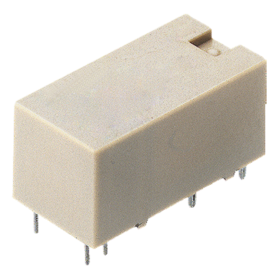
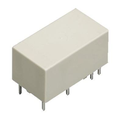
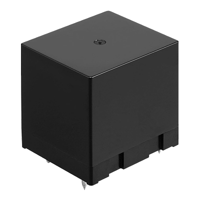
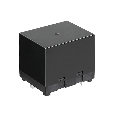
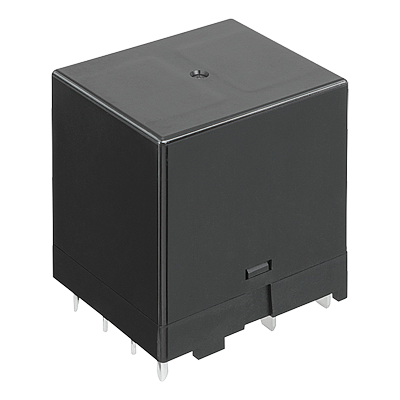
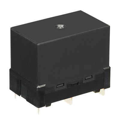
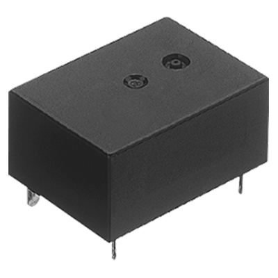
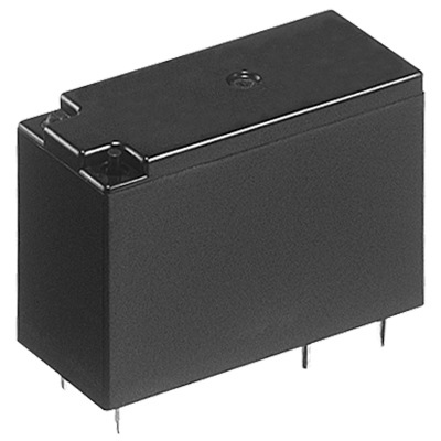
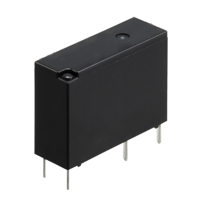
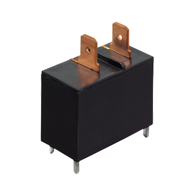
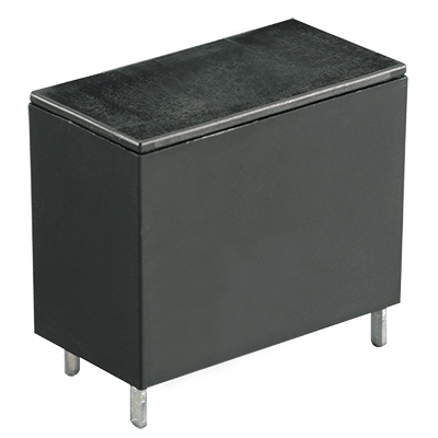
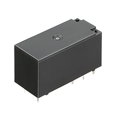
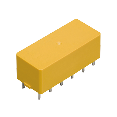
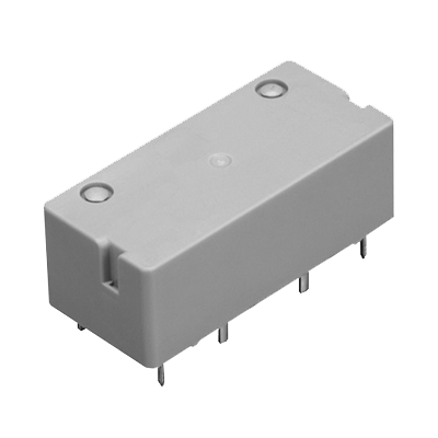
 LQ Relays
Compliant with IEC/EN60335-1*1*2 /EN60079-15*3 1 Form A/1 Form C 10 A small power relays
LQ Relays
Compliant with IEC/EN60335-1*1*2 /EN60079-15*3 1 Form A/1 Form C 10 A small power relays
-
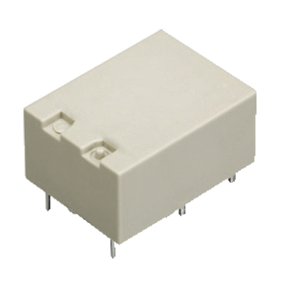
 LZ Relays
Low profile: 15.7 mm, 1 Form A/1 Form C 16 A, Power relay
LZ Relays
Low profile: 15.7 mm, 1 Form A/1 Form C 16 A, Power relay
-
 LZ-N Relays
EN60335-1 GWT compliant, 15.7 mm Low profile, 1 Form A/1 Form C 16 A, Power relays
LZ-N Relays
EN60335-1 GWT compliant, 15.7 mm Low profile, 1 Form A/1 Form C 16 A, Power relays
-
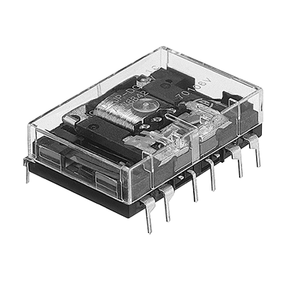 NC Relays
Transistor drive, 2 Form C/4 Form C, 5 A Slim power relays
NC Relays
Transistor drive, 2 Form C/4 Form C, 5 A Slim power relays
-
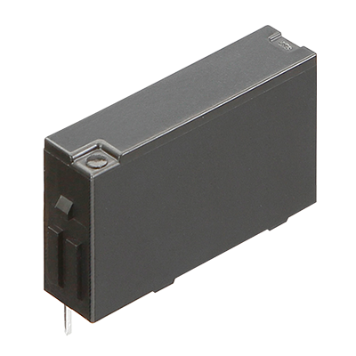 PA-N Relays
Complies with IEC61010 reinforced insulation, For PLC/Interface, 1 Form A 5 A, Slim power relay
PA-N Relays
Complies with IEC61010 reinforced insulation, For PLC/Interface, 1 Form A 5 A, Slim power relay
-
 PF Relays
Compliant with European standards, 1 Form A/1 Form C 6 A, Slim power relays
PF Relays
Compliant with European standards, 1 Form A/1 Form C 6 A, Slim power relays
-
 S Relays
2 Form A 2 Form B/3 Form A 1 Form B/4 Form A /4 A Polarized power relays
S Relays
2 Form A 2 Form B/3 Form A 1 Form B/4 Form A /4 A Polarized power relays
-
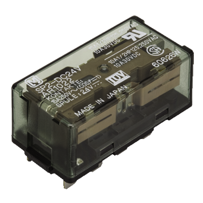 SP Relays
2 Form C 15 A, 4 Form C 10 A, Polarized power relays
SP Relays
2 Form C 15 A, 4 Form C 10 A, Polarized power relays
-
 ST Relays
1 Form A 1 Form B/2 Form A, 8 A, Polarized power relays
ST Relays
1 Form A 1 Form B/2 Form A, 8 A, Polarized power relays
-
- CAD data Catalogs/Datasheets
- FAQ
|
Coil data
- Operating characteristics such as 'Operate voltage' and 'Release voltage'
are influenced by mounting conditions, ambient temperature, etc.
Therefore, please use the relay within ±5% of rated coil voltage. - 'Initial' means the condition of products at the time of delivery.
■ Standard type
| Contact arrangement |
Rated coil voltage |
Operate voltage *1 (at 20°C) |
Release voltage *1 (at 20°C) |
Rated operating current (±10% at 20°C) |
Coil resistance (±10% at 20°C) |
Rated operating power |
Max. allowable voltage |
|---|---|---|---|---|---|---|---|
| 1 Form A | 5 V DC | Max. 75% V of rated coil voltage (initial) |
Min. 5% V of rated coil voltage (initial) |
40 mA | 125 Ω | 200 mW | 130% of rated coil voltage (at 85°C)*2 180% of rated coil voltage (at 20°C) |
| 6 V DC | 33.3 mA | 180 Ω | |||||
| 9 V DC | 22.2 mA | 405 Ω | |||||
| 12 V DC | 16.7 mA | 720 Ω | |||||
| 18 V DC | 11.1 mA | 1,620 Ω | |||||
| 24 V DC | 8.3 mA | 2,880 Ω | |||||
| 1 Form C | 5 V DC | Max. 75% V of rated coil voltage (initial) |
Min. 5% V of rated coil voltage (initial) |
80 mA | 62.5 Ω | 400 mW | 110% of rated coil voltage (at 85°C)*2 150% of rated coil voltage (at 20°C) |
| 6 V DC | 66.7 mA | 90 Ω | |||||
| 9 V DC | 44.4 mA | 202.5 Ω | |||||
| 12 V DC | 33.3 mA | 360 Ω | |||||
| 18 V DC | 22.2 mA | 810 Ω | |||||
| 24 V DC | 16.7 mA | 1,440 Ω |
| *1 | Square, pulse drive. |
|---|---|
| *2 | When using relays in a high ambient temperature, consider the operate voltage rise due to the high temperature (a rise of approx. 0.4% V for each 1°C with 20°C as a reference)and use a coil impressed voltage that is within the maximum applied voltage range. |
■ Inrush /reinforced insulation type
| Contact arrangement | Rated coil voltage |
Operate voltage *1 (at 20°C) |
Release voltage *1 (at 20°C) |
Rated operating current (±10% at 20°C) |
Coil resistance (±10% at 20°C) |
Rated operating power | Max. allowable voltage |
|---|---|---|---|---|---|---|---|
| 1 Form A | 12 V DC | Max. 80% V of rated coil voltage (initial) |
Min. 5% V of rated coil voltage (initial) |
16.7 mA | 720 Ω | 200 mW | 130% of rated coil voltage (at 85°C) *2 180% of rated coil voltage (at 20°C) |
| 24 V DC | 8.3 mA | 2,880 Ω |
| *1 | Square, pulse drive. |
|---|---|
| *2 | When using relays in a high ambient temperature, consider the operate voltage rise due to the high temperature (a rise of approx. 0.4% V for each 1°C with 20°C as a reference) and use a coil impressed voltage that is within the maximum applied voltage range. |
Specifications
| Item | Specifications | |||
|---|---|---|---|---|
| Standard type | Inrush/reinforced insulation type | |||
| Contact data | Contact arrangement | 1 Form A | 1 Form C | 1 Form A |
| Contact resistance (initial) | Max. 100 mΩ (by voltage drop 6 V DC 1 A) | |||
| Contact material | AgNi type | AgSnO2 type (Movable) / AgNi type (Stationary) |
||
| Contact rating (resistive) |
5 A 30 V DC, 10 A 125 V AC, 5 A 250 V AC |
Form A contact: 10 A 125 V AC, 5 A 250 V AC, 5 A 30 V DC Form B contact: 3 A 125 V AC, 2 A 250 V AC, 1 A 30 V DC |
10 A 125 V AC, 8 A 250 V AC, 5 A 30 V DC |
|
| Max. switching power (resistive) | 1,250 VA, 150 W | Form A contact: 1,250 VA, 150 W Form B contact: 500 VA, 30 W |
2,000 VA, 150 W | |
| Max. switching voltage | 250 V AC, 30 V DC | |||
| Max. switching current | 10 A (125 V AC), 5 A (30 V DC) | |||
| Min. switching load (reference value) *1 | 100 mA 5 V DC | |||
| Insulation resistance (initial) | Min. 1,000 MΩ (at 500 V DC, Measured portion is the same as the case of dielectric strength) | |||
| Dielectric strength (initial) | Between open contacts | 1,000 Vrms for 1 min (detection current: 10 mA) |
750 Vrms for 1 min (detection current: 10 mA) |
1,000 Vrms for 1 min (detection current: 10 mA) |
| Between contact and coil | 4,000 Vrms for 1 min (detection current: 10 mA) | |||
| Surge withstand voltage (initial) *2 | Between contact and coil | 8,000 V | ||
| Time characteristics (initial) | Operate time | Max. 20 ms (at rated coil voltage, at 20°C, without bounce) | ||
| Release time | Max. 20 ms (at rated coil voltage, at 20°C, without bounce, with diode) | |||
| Shock resistance | Functional | 294 m/s2 (half-sine shock pulse: 11 ms, detection time: 10 μs) |
196 m/s2 (half-sine shock pulse: 11 ms, detection time: 10 μs) |
294 m/s2 (half-sine shock pulse: 11 ms, detection time: 10 μs) |
| Destructive | 980 m/s2 (half-sine shock pulse: 6 ms) | |||
| Vibration resistance | Functional | 10 to 55 Hz (at double amplitude of 1.6 mm, detection time: 10 μs) | ||
| Destructive | 10 to 55 Hz (at double amplitude of 2 mm) | |||
| Expected life | Mechanical life | Min. 10 x 106 ope. (at 180 times/min) | ||
| Conditions | Conditions for usage, transport and storage *3 | Ambient temperature: -40 to +85°C *4 (-40 to +60°C at our standard packing condition) Humidity: 5 to 85% RH (Avoid icing and condensation) |
||
| Unit weight | Approx. 7 g | |||
| * | Note: Specifications will vary with foreign standards certification ratings. |
|---|
| *1 | This value can change due to the switching frequency, environmental conditions, and desired reliability level, therefore it is recommended to check this with the actual load. |
|---|---|
| *2 | Wave is standard shock voltage of ±1.2 x 50 µs according to JEC-212-1981 |
| *3 | For ambient temperature please read “GUIDELINES FOR RELAY USAGE”. |
| *4 | When using relays in a high ambient temperature, consider the operate voltage rise due to the high temperature (a rise of approx. 0.4% V for each 1°C with 20°C as a reference) and use a coil impressed voltage that is within the maximum applied voltage range. |
Expected electrical life
Condition: Resistive load, at 20°C, at 20 times/min, with diode
| Type | Load | Switching capacity | Number of operations | ||
|---|---|---|---|---|---|
| Standard type | 1 Form A | Resistive load |
5 A 30 V DC | 100 x 103 ope. (Switching frequency ON:OFF=1.5 s:1.5 s) |
|
| 10 A 125 V AC | 50 x 103 ope. (Switching frequency ON:OFF=1.5 s:1.5 s) |
||||
| 5 A 250 V AC | 50 x 103 ope. (Switching frequency ON:OFF=1.5 s:1.5 s) |
||||
| 1 Form C | Form A contact |
5 A 30 V DC | 100 x 103 ope. (Switching frequency ON:OFF=1.5 s:1.5 s) |
||
| 10 A 125 V AC | 50 x 103 ope. (Switching frequency ON:OFF=1.5 s:1.5 s) |
||||
| 5 A 250 V AC | 50 x 103 ope. (Switching frequency ON:OFF=1.5 s:1.5 s) |
||||
| Form B contact |
3 A 125 V AC | 200 x 103 ope. (Switching frequency ON:OFF=1.5 s:1.5 s) |
|||
| 2 A 250 V AC | 200 x 103 ope. (Switching frequency ON:OFF=1.5 s:1.5 s) |
||||
| 1 A 30 V DC | 100 x 103 ope. (Switching frequency ON:OFF=1.5 s:1.5 s) |
||||
| Inrush/reinforced insulation type | 1 Form A | Resistive load |
10 A 250 V AC | 50 x 103 ope. (Switching frequency ON:OFF=1 s:9 s) |
|
| 8 A 250 V AC | 100 x 103 ope. (Switching frequency ON:OFF=1 s:9 s) |
||||
| 5 A 30 V DC | 100 x 103 ope. (Switching frequency ON:OFF=1.5 s:1.5 s) |
||||
| Capacitor load |
inrush 40 A peak/100 μs steady 1 A rms 250 V AC |
100 x 103 ope. (Switching frequency ON:OFF=1 s:9 s) |
|||
| Motor load |
inrush 30 A peak/0.5 s steady 3 A rms cosφ=0.5 250 V AC |
300 x 103 ope. (Switching frequency ON:OFF=1 s:9 s) |
|||
Insulation Characteristic (IEC61810-1)
| Item | Characteristics | |
|---|---|---|
| Clearance/Creepage distance (IEC61810-1) | Standard type | 1 Form A: Min. 4.0 mm/Min. 4.0 mm, 1 Form C: Min. 3.5 mm/Min. 3.5 mm |
| Inrush/reinforced insulation type | Min. 5.5 mm/5.5 mm | |
| Category of protection (IEC61810-1) | RT Ⅲ | |
| Tracking resistance (IEC60112) | PTI 175 | |
| Insulation material group | Ⅲa | |
| Over voltage category | Ⅲ | |
| Rated voltage | 250 V | |
| Pollution degree | 2 | |
| Type of insulation (Between contact and coil) | Standard type | Basic insulation |
| Inrush/reinforced insulation type | Reinforced insulation | |
| Type of insulation (Between open contacts) | Micro disconnection | |
Note) Standard type: Actual value
Inrush/reinforced insulation type: EN/IEC VDE certified.
|
CONTACT US
If you have any questions, please select the option below to contact us or find answers.
CONTACT US
BY EMAIL
BY EMAIL
Please click your area to select country or region


Related Information
Service & Support
Requests to customers (Automation Control Components & Industrial Device) [Excluding specific product]
Requests to customers (Automation Control Components & Industrial Device) [For specific product]
Requests to customers (FA Sensors & Components [Excluding motors])
Requests to customers (Dedicated to industrial motors)
- COMPONENTS & DEVICES
- FA SENSORS & COMPONENTS
- Fiber Sensors
- Photoelectric Sensors / Laser Sensors
- Micro Photoelectric Sensors
- Light Curtains / Safety Components
- Area Sensors
- Inductive Proximity Sensors
- Particular Use Sensors
- Sensor Options
- Wire-Saving Systems
- Programmable Controllers / Interface Terminal
- Human Machine Interface
- Pressure Sensors / Flow Sensors
- Measurement Sensors
- Static Control Devices
- Laser Markers / 2D Code Readers
- Machine Vision System
- Energy Management Solutions
- Timers / Counters / FA Components
- MOTORS
![]()