[Notification of CAD Data Download Issue]
We regret to inform you that we are currently experiencing issues with downloading CAD data for some products.
We are investigating the cause of this problem. We apologize for any inconvenience this may cause and appreciate your understanding.

 Business
> Industrial Devices
> Automation Controls Top
> Components & Devices
> Switches
> Non Seal Type Switches
> AVT3/AVL3 (FS-T) Switches
> Rating/Performance
Business
> Industrial Devices
> Automation Controls Top
> Components & Devices
> Switches
> Non Seal Type Switches
> AVT3/AVL3 (FS-T) Switches
> Rating/Performance
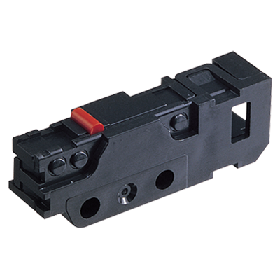
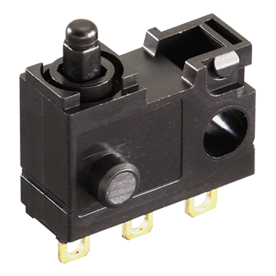
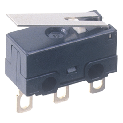
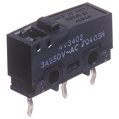
AVT3/AVL3 (FS-T) Switches
-
Lineup
-
 AV6 (CS) Switches
Subminiature Size Connector Integrated Type
AV6 (CS) Switches
Subminiature Size Connector Integrated Type
-
 AEQ (EQ) Switches
Sliding contact construction Switches for Low-level Loads
AEQ (EQ) Switches
Sliding contact construction Switches for Low-level Loads
-
 AH1 (FJ) Switches
Ultra-miniature Size Switches High Precision
AH1 (FJ) Switches
Ultra-miniature Size Switches High Precision
-
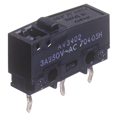
 AV3/AVM3 (FS) Switches
Subminiature Size Switches with Excellent Operating Position Accuracy
AV3/AVM3 (FS) Switches
Subminiature Size Switches with Excellent Operating Position Accuracy
-
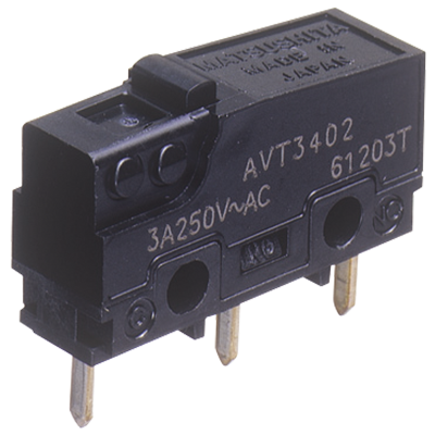 AVT3/AVL3 (FS-T) Switches
Subminiature Size Switches with Excellent Operating Position Accuracy
AVT3/AVL3 (FS-T) Switches
Subminiature Size Switches with Excellent Operating Position Accuracy
-
 AV3 (FS) Switches Contact gap 1 mm Type
Subminiature Size Door Inter-lock Switches
AV3 (FS) Switches Contact gap 1 mm Type
Subminiature Size Door Inter-lock Switches
-
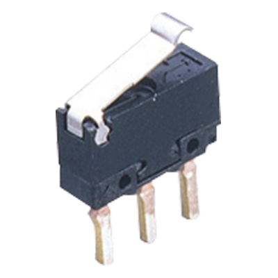 AV4 (FU) Switches
Ultra-miniature Size, Light-weight Snap action Switches
AV4 (FU) Switches
Ultra-miniature Size, Light-weight Snap action Switches
-
- CAD data Catalogs/Datasheets
- FAQ
|
Contact Rating
Standard version
| Type | Standard version | |||
|---|---|---|---|---|
| Contact specification |
AgNi alloy contact type Plunger color: Black |
Au-clad contact type | ||
| Triple layer contact type Plunger color: Red |
Double layer contact type For low-level circuit Plunger color: Green |
|||
| Load style Contact voltage |
Resistive load (cos φ ≒ 1) |
Inductive load (cos φ ≒ 0.6 to 0.7) |
Resistive load (cos φ ≒ 1) |
Inductive load (cos φ ≒ 1) |
| 125V AC | 3A | 2A | 0.1A | - |
| 250V AC | 3A | 2A | 0.1A | - |
| 30V DC | 3A | 2A | 0.1A | 0.1A |
| 125V DC | 0.4A | 0.05A | - | - |
| * | Note: Time constant shall be less than 7 msec. for DC inductive loads. |
|---|
Long life version
| Type | Long life version | |||
|---|---|---|---|---|
| Contact specification |
AgNi alloy contact type Plunger color: Black |
Au-clad contact type | ||
| Triple layer contact type Plunger color: Red |
Double layer contact type For low-level circuit Plunger color: Green |
|||
| Load style Contact voltage |
Resistive load (cos φ ≒ 1) |
Inductive load (cos φ ≒ 0.6 to 0.7) |
Resistive load (cos φ ≒ 1) |
Inductive load (cos φ ≒ 1) |
| 125V AC | 5A | 3A | 0.1A | - |
| 250V AC | 5A | 3A | 0.1A | - |
| 30V DC | 5A | 3A | 0.1A | 0.1A |
| 125V DC | 0.4A | 0.05A | - | - |
| * | Note: Time constant shall be less than 7 msec. for DC inductive loads. |
|---|
|
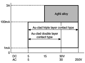
| * | If the contact is being used in the constant low-level circuit load range, the Au-clad double layer contact type is recommended. If there is a danger of the current being less than 0.5 A, for instance if the contact is being turned on and off, the Au-clad triple layer contact type is recommended. The diagram above is intended as a reference. Please use the product within the rated voltage and current. |
|---|
Low-level circuit rating (Au-clad contact type)
| Rated voltage | Resistive load |
|---|---|
| 6 V DC | 5 mA |
| 12 V DC | 2 mA |
| 24 V DC | 1 mA |
Characteristics
| Item | Standard version | Long life version | Test condition | |||
|---|---|---|---|---|---|---|
| AgNi alloy contact type |
Au-clad contact type |
AgNi alloy contact type | Au-clad contact type | |||
| Expected life |
Mechanical life | Min. 5 × 10⁵ (OTmax.) | Min. 3 × 10⁷ (OT: Specified value) Min. 107 (OTmax.) |
at 60 cpm | ||
| Electrical life | Min. 5 × 10⁴ | Min. 2 × 10⁵ | 5 × 10⁴ | 2 × 10⁵ | at 20 cpm, at rated load, OT max. | |
| Insulation resistance | Min.100MΩ | at 500V DC | ||||
| Dielectric strength |
Between non-continuous terminals | 1,000 Vrms | ||||
| Between each terminal and other exposed metal parts | 1,500 Vrms | |||||
| Between each terminal and ground | 1,500 Vrms | |||||
| Contact resistance (Initial) | Max. 50 mΩ | Max. 100 mΩ | Max. 50 mΩ | Max. 100 mΩ | Ag alloy contact type: by voltage drop 1 A, 6 to 8V DC Au-clad contact type: by voltage drop 0.1 A, 6 to 8V DC |
|
| Vibration resistance (Pin plunger type) | 10 to 55 Hz at single amplitude of 0.75mm | Contact opening: Max. 1 msec. | ||||
| Shock resistance (Pin plunger type) | 294 m/s2 min. (OF 0.98 N type) 147 m/s2 min. (OF 0.49 N type) |
294 m/s2 min. (OF 0.98 N type) 147 m/s2 min. (OF 0.49 N type) 49 m/s2 min. (OF 0.25 N type) |
Min. 294 m/s2 | Min. 294 m/s2 | Contact opening: 1 msec. max. | |
| Allowable operating speed (no load) | 0.1 to 1,000 mm/sec. | |||||
| Max.operating cycle rate (no load) | 300 cpm | |||||
| Ambient temperature | –25°C to +85°C | no freezing and condensing | ||||
| Unit weight | Approx.2g | |||||
| Protection grade | IP40 | |||||
| * | Test conditions and judgement are complying with “NECA C 4505”. |
|---|
Operating characteristics
1.Pin plunger
| 4th digit number of Part No. |
Operating Force (OF) Max. | Release Force (RF) Min. | Pretravel (PT) Max. | Movement Differential (MD) Max. | Overtravel (OT) Min. | Operating Position (OP) |
|---|---|---|---|---|---|---|
| 0 | 0.25N | 0.020N | 0.6mm | 0.1mm | 0.4mm | Distance from mounting holes: 8.4±0.3mm Distance from stand-off: FS 11.8±0.4mm FS-T 11.7±0.4mm |
| 2 | 0.49N | 0.074N | ||||
| 4 | 0.98N | 0.15N | ||||
| 5 | 1.47N | 0.20N |
2.Short hinge lever
| 4th digit number of Part No. |
Operating Force (OF) Max. | Release Force (RF) Min. | Pretravel (PT) Max. | Movement Differential (MD) Max. | Overtravel (OT) Min. | Operating Position (OP) |
|---|---|---|---|---|---|---|
| 0 | 0.098N | 0.004N | 2.5mm | 0.5mm | 0.8mm | Distance from mounting holes: 8.8±0.8mm Distance from stand-off: FS 12.2±0.9mm FS-T 12.1±0.9mm |
| 2 | 0.20N | 0.017N | ||||
| 4 | 0.39N | 0.034N | ||||
| 5 | 0.59N | 0.039N |
3.Hinge lever
| 4th digit number of Part No. |
Operating Force (OF) Max. | Release Force (RF) Min. | Pretravel (PT) Max. | Movement Differential (MD) Max. | Overtravel (OT) Min. | Operating Position (OP) |
|---|---|---|---|---|---|---|
| 0 | 0.078N | 0.003N | 2.8mm | 0.8mm | 1.2mm | Distance from mounting holes: 8.8±0.8mm Distance from stand-off: FS 12.2±0.9mm FS-T 12.1±0.9mm |
| 2 | 0.16N | 0.015N | ||||
| 4 | 0.34N | 0.029N | ||||
| 5 | 0.54N | 0.034N |
4.Long hinge lever
| 4th digit number of Part No. |
Operating Force (OF) Max. | Release Force (RF) Min. | Pretravel (PT) Max. | Movement Differential (MD) Max. | Overtravel (OT) Min. | Operating Position (OP) |
|---|---|---|---|---|---|---|
| 0 | - | - | 3.5mm | 1.0mm | 1.6mm | Distance from mounting holes: 8.8±1.2mm Distance from stand-off: FS 12.2±1.3mm FS-T 12.1±1.3mm |
| 2 | 0.12N | 0.012N | ||||
| 4 | 0.25N | 0.025N | ||||
| 5 | 0.44N | 0.029N |
5.Simulated roller lever
| 4th digit number of Part No. |
Operating Force (OF) Max. | Release Force (RF) Min. | Pretravel (PT) Max. | Movement Differential (MD) Max. | Overtravel (OT) Min. | Operating Position (OP) |
|---|---|---|---|---|---|---|
| 0 | - | - | 2.8mm | 0.8mm | 1.2mm | Distance from mounting holes: 11.65±0.8mm Distance from stand-off: FS 15.05±0.9mm FS-T 14.95±0.9mm |
| 2 | 0.16N | 0.015N | ||||
| 4 | 0.34N | 0.029N | ||||
| 5 | 0.54N | 0.034N |
6.Roller lever
| 4th digit number of Part No. |
Operating Force (OF) Max. | Release Force (RF) Min. | Pretravel (PT) Max. | Movement Differential (MD) Max. | Overtravel (OT) Min. | Operating Position (OP) |
|---|---|---|---|---|---|---|
| 0 | - | - | 2.5mm | 0.5mm | 0.8mm | Distance from mounting holes: 14.5±0.8mm Distance from stand-off: FS 17.9±0.9mm FS-T 17.8±0.9mm |
| 2 | 0.20N | 0.017N | ||||
| 4 | 0.39N | 0.034N | ||||
| 5 | 0.59N | 0.039N |
|
Related Information
BY EMAIL


Requests to customers (Automation Control Components & Industrial Device) [Excluding specific product]
Requests to customers (Automation Control Components & Industrial Device) [For specific product]
Requests to customers (FA Sensors & Components [Excluding motors])
Requests to customers (Dedicated to industrial motors)
- COMPONENTS & DEVICES
- FA SENSORS & COMPONENTS
- Fiber Sensors
- Photoelectric Sensors / Laser Sensors
- Micro Photoelectric Sensors
- Light Curtains / Safety Components
- Area Sensors
- Inductive Proximity Sensors
- Particular Use Sensors
- Sensor Options
- Wire-Saving Systems
- Programmable Controllers / Interface Terminal
- Human Machine Interface
- Pressure Sensors / Flow Sensors
- Measurement Sensors
- Static Control Devices
- Laser Markers / 2D Code Readers
- Machine Vision System
- Energy Management Solutions
- Timers / Counters / FA Components
- MOTORS
![]()