General Purpose & Slim Body Area Sensor NA2-N
Partly Order Discontinued
Products that have obtained Korea's S-mark certification NA2-N-K
 |
June 30, 2023 |
|
|
Cautions For Use
- Never use this product as a sensing device for personnel protection.
- For sensing devices to be used as safety devices for press machines or for personnel protection, use products which meet standards, such as OSHA, ANSI or IEC etc., for personnel protection applicable in each region or country.
- If this product is used as a sensing device for personnel protection, death or serious body injury could result.
- For a product which meets safety standards, use the safety light curtain.
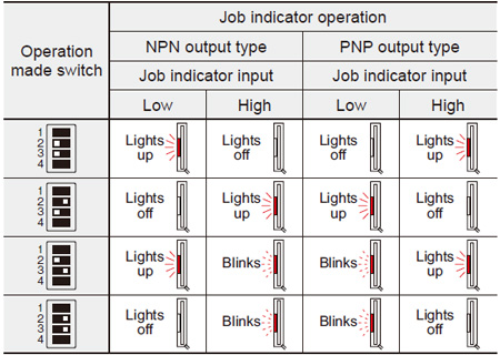
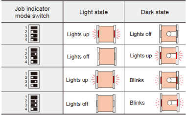
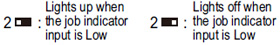
Job indicator operation selection
- The operation of the job indicator can be selected with job indicator mode switch.
| Job indicator input signal condition |
| Type |
Signal |
Signal condition |
| NPN output |
Low |
0 to 2 V |
| High |
5 to 30 V, or open (Note) |
| PNP output |
Low |
0 to 2 V, or open (Note) |
| High |
8 V to +V |
| Note: |
Insulate the wire if it is kept open. |
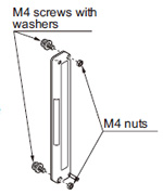
Mounting
- Use M4 screws with washers and M4 nuts. The tightening torque should be 0.5 N·m or less. During mounting, do not apply any bending or twisting force to the sensor.
(Purchase the screws and nuts separately.) |
|
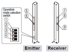
Functional description
| |
Description |
Function |
| Emitter |
① |
Emission frequency selection switch |
 |
| ② |
Job indicator mode switch |
 |
| ③ |
 |
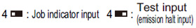
| ④ |
Job indicator / Test input
(emission halt input)
selection switch |
 |
| ⑤ |
Job indicator
(Red LED) |
Lights up, blinks or lights off when the job indicator input is applied, selected by operation mode switch. |
| ⑥ |
Emitting indicator
(Green LED × 2) |
Light up during emission; one LED lights up for Frequency A setting, both LEDs light up for Frequency B setting. |
| Receiver |
⑦ |
Job indicator
(Red LED) |
Lights up, blinks or lights off when the job indicator input is applied, selected by operation mode switch. |
| ⑧ |
Stable incident beam indicator
(Green LED) |
Lights up when all beam channels are stably received. |
When an excess current flows through the output, the stable incident beam indicator and the operation indicator on the receiver blink simultaneously due to the operation of the short-circuit
protection circuit. |
| ⑨ |
Operation indicator
(Red LED) |
Lights up when one or more beam channels are interrupted. |
To use job indicator as large operation indicator
- The job indicators can be used as large operation indicators by setting No. 4 of the operation mode switch to the OFF side and connecting the input (pink) of the emitter to the output (black) of the receiver.
| Note: |
In order to use the job indicators as large operation indicators, make sure to set No. 4 of the operation mode switch to the OFF side. If it is set to the ON side, the job indicator does not light up or blink. |
Orientation
- The emitter and the receiver must face each other correctly. If they are set upside down, the sensor does not work.
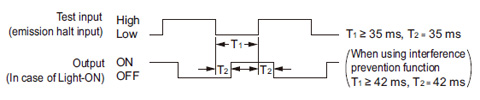
Test input (emission halt) function
- The emission is stopped when No. 4 of the operation mode switch is set to the ON side and the input (pink) of the emitter is made High (PNP output type: Low).
Since the output can be turned ON / OFF without the sensing object, this function is useful for start-up inspection. If the output follows the application / withdrawal of the test input (emission halt input), the sensor operation is normal, else it is abnormal.
| Operation mode switch setting |
| OFF |
ON |
 |
 |
Notes:
| 1) |
When the test input (emission halt) function is set, the job indicator (red) does not light up or blink. |
| 2) |
When emission is stopped during the test input (emission halt) function, the emitter’s emitting indicator (green) does not light up. |
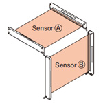
Interference prevention function
Wiring
- Make sure that the power supply is off while wiring.
- Verify that the supply voltage variation is within the rating.
- If power is supplied from a commercial switching regulator, ensure that the frame ground (F.G.) terminal of the power supply is connected to an actual ground.
- In case noise generating equipment (switching regulator, inverter motor, etc.) is used in the vicinity of this sensor, connect the frame ground. (F.G.) terminal of the equipment to an actual ground.
- Do not run the wires together with high-voltage lines or power lines or put them in the same raceway. This can cause malfunction due to induction.
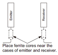
Use conditions to comply with CE Marking
- Following work must be done in case of using this product as a CE marking (European standard EMC Directire) conforming product.
Place ferrite core at the sensor cable.
|
|
Prepare 2 pcs. of the following recommended ferrite core (or an equivalent product.)
<Recommended product>
- ESD-SR-110 [NEC TOKIN Corporation]
- ZCAT1730-0730A(-BK) [TDK Corporation]
- E04SR170730A
[SEIWA ELECTRIC MFG. CO., LTD.] |
Others
- Do not use during the initial transient time (500 ms) after the power supply is switched on.
- Avoid dust, dirt and steam.
- Take care that the sensor does not come in direct contact with water, oil, grease, or organic solvents, such as, thinner, etc.
- Take care that the sensor is not directly exposed to fluorescent light from a rapid-starter lamp or a high frequency lighting device, as it may affect the sensing performance.
Return to top
Return to top

 Business
> Industrial Devices
> Automation Controls Top
> FA Sensors & Components
> Sensors
> Area Sensors
> General Purpose & Slim Body Area Sensor NA2-N
> Cautions For Use
Business
> Industrial Devices
> Automation Controls Top
> FA Sensors & Components
> Sensors
> Area Sensors
> General Purpose & Slim Body Area Sensor NA2-N
> Cautions For Use