[Notification of CAD Data Download Issue]
We regret to inform you that we are currently experiencing issues with downloading CAD data for some products.
We are investigating the cause of this problem. We apologize for any inconvenience this may cause and appreciate your understanding.

 Business
> Industrial Devices
> Automation Controls Top
> Components & Devices
> Relays / Couplers
> High-capacity DC Cutoff Relay
> HE-V Relays
> Rating/Performance
Business
> Industrial Devices
> Automation Controls Top
> Components & Devices
> Relays / Couplers
> High-capacity DC Cutoff Relay
> HE-V Relays
> Rating/Performance
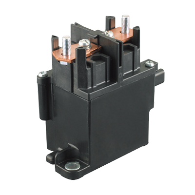
HE-V Relays
-
Lineup
-
 EP Relays
High capacity of Max. 1,000 V DC Cut-off possible
EP Relays
High capacity of Max. 1,000 V DC Cut-off possible
-
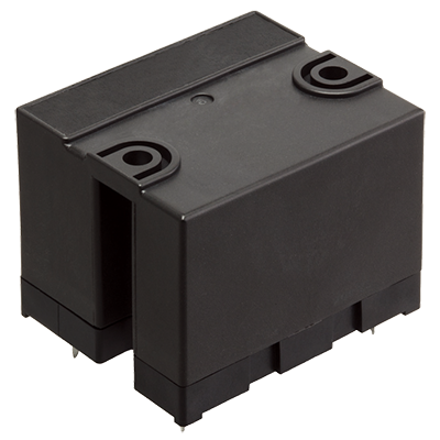 HE-V Relays
Max. 1,000 V DC, 20 A cut-off possible, High capacity DC power relays
HE-V Relays
Max. 1,000 V DC, 20 A cut-off possible, High capacity DC power relays
-
- CAD data Catalogs/Datasheets
- FAQ
|
Coil data
- Operating characteristics such as 'Operate voltage' and 'Release voltage' are influenced by mounting conditions, ambient temperature, etc.
Therefore, please use the relay within ±5% of rated coil voltage. - 'Initial' means the condition of products at the time of delivery.
| Rated coil voltage |
Operate voltage* (at 20°C) |
Release voltage* (at 20°C) |
Rated operating current (±10%, at 20°C) |
Coil resistance (±10%, at 20°C) |
Rated operating power |
Max. allowable voltage (at 55°C) |
|---|---|---|---|---|---|---|
| 6 V DC | Max. 70% V of rated coil voltage (Initial) |
Min. 5% V of rated coil voltage (Initial) |
320 mA | 18.8 Ω | 1,920 mW | 110% V of rated coil voltage |
| 9 V DC | 213 mA | 42.2 Ω | ||||
| 12 V DC | 160 mA | 75 Ω | ||||
| 15 V DC | 128 mA | 117 Ω | ||||
| 24 V DC | 80 mA | 300 Ω |
| * | square, pulse drive |
|---|
Specifications
| Item | Specifications | |
|---|---|---|
| Contact data | Contact arrangement | 2 Form A |
| Contact resistance (initial) |
Max. 100 mΩ (by voltage drop 6 V DC 1 A) Max. 3 mΩ (by voltage drop 6 V DC 20 A, reference value) |
|
| Contact material | AgNi type | |
| Contact rating (resistive) |
20 A 800 V DC, 25 A 600 V DC (at contact connected in series) 20 A 400 V DC (at 1 Form A contact only) |
|
| Max. switching voltage | 1,000 V DC | |
| Max. switching current | 25 A | |
| Min. switching load (reference value) *1 |
100 mA 5 V DC | |
| Insulation resistance (initial) | Min. 1,000 MΩ (at 1,000 V DC, Measured portion is the same as the case of dielectric strength.) |
|
| Short current (initial) | Max. 300 A 1 ms (reference value) | |
| Dielectric strength (initial) |
Between open contacts |
2,000 Vrms for 1 min (detection current: 10 mA) |
| Between contact sets |
4,000 Vrms for 1 min (detection current: 10 mA) | |
| Between contact and coil |
5,000 Vrms for 1 min (detection current: 10 mA) | |
| Surge withstand voltage (initial)*2 | Between contact and coil |
10,000 V |
| Coil holding voltage *3 | 33 to 110% V (at -40 to +55°C: contact carrying current 25 A) 33 to 60% V (at -40 to +85°C: contact carrying current 25 A) |
|
| Time characteristic (initial) |
Operate time | Max. 30 ms at rated coil voltage (at 20°C, without bounce) |
| Release time | Max. 10 ms at rated coil voltage (at 20°C, without bounce, without diode) | |
| Shock resistance |
Functional | 98 m/s2 (half-sine shock pulse: 11 ms, detection time: 10 μs) |
| Destructive | 980 m/s2 (half-sine shock pulse: 6 ms) | |
| Vibration resistance | Functional | 10 to 55 Hz (at double amplitude of 1 mm, detection time: 10 μs) |
| Destructive | 10 to 55 Hz (at double amplitude of 1.5 mm) | |
| Expected life | Mechanical life | Min. 106 ope. (switching frequency: at 180 times/min) |
| Conditions | Conditions for usage, transport and storage *4 |
Ambient temperature: -40 to +55°C (when coil holding voltage is 33% to 110% of rated coil voltage) -40 to +85°C (when coil holding voltage is 33% to 60% of rated coil voltage) Humidity: 5 to 85% RH (Avoid icing and condensation) |
| Unit weight | Approx. 120 g | |
| *1 | This value can change due to the switching frequency, environmental conditions, and desired reliability level, therefore it is recommended to check this with the actual load. |
|---|---|
| *2 | Wave is standard shock voltage of ±1.2 x 50 µs according to JEC-212-1981. |
| *3 | Coil holding voltage is the coil voltage after 100 ms following application of the nominal coil voltage. |
| *4 | For ambient temperature, please read "GUIDELINES FOR RELAY USAGE". |
Expected electrical life
1. Contact connected in series
Conditions: at 20°C (L/R ≦ 1 ms), switching frequency ON : OFF = 1 s : 9 s
| Load | Switching capacity | Number of operations |
|---|---|---|
| Resistive load | 20 A 600 V DC | Min. 10 x 103 ope. |
| 20 A 800 V DC | Min. 103 ope. | |
| 25 A 600 V DC | Min. 6 x 10³ ope. | |
| Overload | 20 A 1,000 V DC | Min. 10 ope. |
| Reverse direction | -20 A 400 V DC | Min. 103 ope. |
| Inrush resistance current | 40 A 800 V DC | Min. 103 ope. |
2. 1 Form A contact only
Conditions: at 20°C (L/R ≦ 1 ms), switching frequency ON : OFF = 1 s : 9 s
| Load | Switching capacity | Number of operations |
|---|---|---|
| Resistive load | 20 A 300 V DC | Min. 10 x 103 ope. |
| 20 A 400 V DC | Min. 103 ope. | |
| Overload | 20 A 500 V DC | Min. 10 ope. |
| Reverse direction | -20 A 200 V DC | Min. 103 ope. |
| Inrush resistance current | 40 A 400 V DC | Min. 103 ope. |
Recommended circuit
Positive polarity of load should be connected to pin 1 and pin 3, refer to the following circuit schematics.
1. Contact connected in series (BOTTOM VIEW)
|
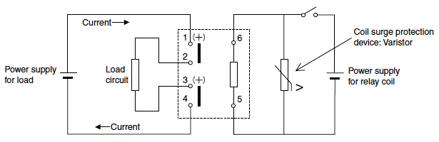
2. 1 Form A contact only (BOTTOM VIEW)
|

|
Related Information
BY EMAIL
- U.S.A.
- +1-800-344-2112
- Europe
- +49-89-45354-1000
- China
- +86-10-59255988
- Singapore
- +65-6299-9181


Requests to customers (Automation Control Components & Industrial Device) [Excluding specific product]
Requests to customers (Automation Control Components & Industrial Device) [For specific product]
Requests to customers (FA Sensors & Components [Excluding motors])
Requests to customers (Dedicated to industrial motors)
- COMPONENTS & DEVICES
- FA SENSORS & COMPONENTS
- Fiber Sensors
- Photoelectric Sensors / Laser Sensors
- Micro Photoelectric Sensors
- Light Curtains / Safety Components
- Area Sensors
- Inductive Proximity Sensors
- Particular Use Sensors
- Sensor Options
- Wire-Saving Systems
- Programmable Controllers / Interface Terminal
- Human Machine Interface
- Pressure Sensors / Flow Sensors
- Measurement Sensors
- Static Control Devices
- Laser Markers / 2D Code Readers
- Machine Vision System
- Energy Management Solutions
- Timers / Counters / FA Components
- MOTORS
![]()