【Notification of Manufacturer Change for Panasonic Industrial Devices SUNX Products and Panasonic Industrial Devices SUNX Tatsuno Products】
From April 1, 2024, the terms "Panasonic Industrial Devices SUNX Co., Ltd." and "Panasonic Industrial Devices SUNX Tatsuno Co., Ltd."
in this page and in the manuals and other documents to be downloaded will all be replaced with "Panasonic Industry Co., Ltd." and applied accordingly.
Amplifier-separated Type Digital Laser Sensor LS-500
Cautions For Use
| ・ |
This website is a guide to select a suitable product.
Be sure to read the instruction manual attached to the product prior to its use. |
- Never use this product as a sensing device for personnel protection.
- In case of using sensing devices for personnel protection, use products which meet regulations and standards, such as OSHA, ANSI or IEC etc., for personnel protection applicable in each region or country.
- Do not operate products using methods other than the ones described in the instruction manual included with each product. Control or adjustment through procedures other than the ones specified may cause hazardous laser radiation exposure.
Cautions for laser beams
- This product is a class 1 laser product according to IEC/EN/JIS/GB/KS standards and FDA regulations*.
- Avoid observing beams in a dark surrounding environment.
- Do not look at beams using an optical device such as an optical telephoto system.
- The following label is affixed to the emitter of this product. Handle the product according to the instruction given on the label.
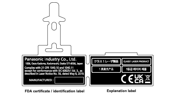
| * | This product complies with the FDA regulations (FDA 21 CFR 1040.10 and 1040.11) in accordance with FDA Laser Notice No. 56, except for complying with IEC 60825-1 Ed. 3. |
|---|
Safety standards for laser beam products
- For the purpose of preventing any injury which may occur to the user by the use of the laser product in advance, the following standards have been established by the IEC Standards, EN Standards, JIS Standards, GB Standards, KS Standards and FDA Regulations.
| |
IEC |
: IEC 60825-1:2014 |
| |
EN |
: EN 60825-1:2014/A11:2021 |
| |
JIS |
: JIS C 6802:2014 |
| |
GB |
: GB 7247.1-2012 |
| |
KS |
: KS C IEC 60825-1:2014 |
| |
FDA |
: PART 1040.10, 1040.11(Laser Notice No.56 applied) |
| These standards classifies laser products according to the level of hazard and
provide the safety measures for respective classes. Based on the above standards, the LS-H□
series is classified as a Class 1 laser product. |
| Classification |
Description |
| Class 1 |
Lasers that are safe under reasonably foreseeable conditions of operation, including the use of optical instruments for intrabeam viewing. |
Note: When an unexpected failure occurs, dangerous radiation may be generated. Therefore, pay special attention to safety.
Safe use of laser products
- For the purpose of preventing users from suffering injuries by laser products, each standard stipulates (Safety of laser products). Kindly check the standards before use.
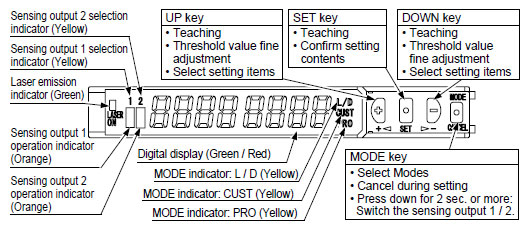
Part description (Amplifier)
Mounting
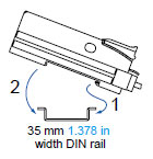
<How to mount the amplifier>
| (1) |
Fit the rear part of the mounting section of the amplifier on a 35 mm 1.378 in width DIN rail. |
| (2) |
Press down the rear part of the mounting section of the unit on the 35 mm 1.378 in width DIN rail and fit the front part of the mounting section to the DIN rail. |
|
|
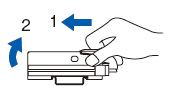
<How to remove the amplifier>
| (1) |
Push the amplifier forward. |
| (2) |
Lift up the front part of the amplifier to remove it. |
| Note: |
Be careful. If the front part is lifted without pushing the amplifier forward, the hook on the rear portion of the mounting section is likely to break. |
|
|
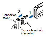
<How to mount the sensor head>
| (1) |
Insert the sensor head connector into the inlet until it clicks. |
| (2) |
Fit the cover to the connector. |
|
|
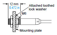
- The tightening torque should be 0.98 N·m or less.
|
|
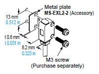
- In case mounting this product, use a metal plate MS-EXL2-2 (accessory).
- The tightening torque should be 0.5 N·m or less with M3 screws.
|
|
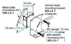
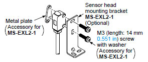
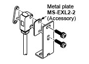
- In case using the dedicated sensor head mounting bracket MS-EXL2-1 (optional) when mounting this product, the metal plate
MS-EXL2-2 (accessory) is required depending on the mounting direction. Mount as the diagram below indicates.
<Not requiring the metal plate> |
|---|
 |
|
|
<Requiring the metal plate> |
|---|
 |
|
|
- The tightening torque should be 0.5 N・m or less.
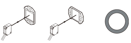
- When placing the sensor head horizontally or vertically, the reflector must also be positioned horizontally or vertically as shown in Fig. 1 below.
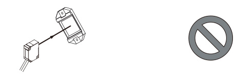
If the sensor head is placed horizontally or vertically but the reflector is tilted as shown in Fig. 2 below, the reflection amount will decrease, which may cause unstable detection.
|
|
| Fig. 1 Proper positioning |
When placing the sensor head horizontally or vertically, the reflector shall also be positioned horizontally or vertically.
<Correct> |
 |
|
| Fig. 2 Improper positioning |
When placing the reflector tilted even when the sensor head is positioned horizontally or vertically.
<Incorrect> |
 |
|
Wiring
- Make sure that the power supply is off while wiring.
- Verify that the supply voltage variation is within the rating.
- Take care that if a voltage exceeding the rated range is applied, or if an AC power supply is directly connected, the sensor may get burnt or damaged.
- If power is supplied from a commercial switching regulator, ensure that the frame ground (F.G.) terminal of the power supply is connected to an actual ground.
- In case noise generating equipment (switching regulator, inverter motor, etc.) is used in the vicinity of this product, connect the frame ground (F.G.) terminal of the equipment to an actual ground.
- Take care that short-circuit or wrong wiring of the load may burn or damage the sensor
- Do not run the wires together with high-voltage lines or power lines or put them in the same raceway. This can cause malfunction due to
induction.
- Ensure that an isolation transformer is utilized for the DC power supply. If an auto transformer is utilized, the main amplifier or power supply may be damaged.
- Make sure to use the optional quick-connection cable for the connection of the amplifier [connector type LS-501(P)]. Extension up to total 100 m 328.084 ft is possible with 0.3 mm2, or more, cable. However, in order to reduce noise, make the wiring as short as possible. Set the supply voltage after considering the voltage drop caused by the cable’s resistance. When adding units, wiring length must not exceed 50 m 164.042 ft (for 5 to 8 amplifiers) or 20 m 65.617 ft (for 9 to 16 amplifiers).
Others
- Do not use during the initial transient time (0.5 sec. approx.) after the power supply is switched on.
- Because the sensitivity is higher in U-LG and HYPER modes than in other modes, it can be more easily affected by extraneous noise. Check the operating environment before use.
- This sensor is suitable for indoor use only.
- Avoid dust, dirt, and steam.
- Take care that the product does not come in direct contact with water, oil, grease, or organic solvents, such as, thinner, etc.
- This sensor cannot be used in an environment containing inflammable or explosive gasses.
- Never disassemble or modify the sensor.
Return to top
Return to top

 Business
> Industrial Devices
> Automation Controls Top
> FA Sensors & Components
> Sensors
> Photoelectric Sensors / Laser Sensors
> Amplifier-separated Type Digital Laser Sensor LS-500
> Cautions For Use
Business
> Industrial Devices
> Automation Controls Top
> FA Sensors & Components
> Sensors
> Photoelectric Sensors / Laser Sensors
> Amplifier-separated Type Digital Laser Sensor LS-500
> Cautions For Use