【Notification of Manufacturer Change for Panasonic Industrial Devices SUNX Products and Panasonic Industrial Devices SUNX Tatsuno Products】
From April 1, 2024, the terms "Panasonic Industrial Devices SUNX Co., Ltd." and "Panasonic Industrial Devices SUNX Tatsuno Co., Ltd."
in this page and in the manuals and other documents to be downloaded will all be replaced with "Panasonic Industry Co., Ltd." and applied accordingly.

 Business
> Industrial Devices
> Automation Controls Top
> FA Sensors & Components
> Sensors
> Light Curtains / Safety Components
> Compact & Robust Safety Light Curtain [Type 4 PLe SIL3] SF4D
> Cautions For Use
Business
> Industrial Devices
> Automation Controls Top
> FA Sensors & Components
> Sensors
> Light Curtains / Safety Components
> Compact & Robust Safety Light Curtain [Type 4 PLe SIL3] SF4D
> Cautions For Use
Compact & Robust Safety Light Curtain [Type 4 PLe SIL3] SF4D
Cautions For Use
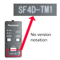
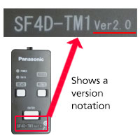
Compatibility with communication module SF4D-TM1 for SF4D series
Please note that it doesn't work when connecting the communication module SF4D-TM1 manufactured before November 2019 to Type 4 Compact & Robust Safety Light Curtain SF4D series Ver.3.0 manufactured after March 17, 2020.
Compatibility of SF4D Ver. and SF4D-TM1
| SF4D Ver. 2.0 (manufactured before March 16, 2020) |
SF4D Ver. 3.0 (manufactured after March 17, 2020) |
|
|---|---|---|
| SF4D-TM1 (manufactured before November 2019) |
Yes | No |
| SF4D-TM1 Ver. 2.0 (manufactured after December 2019) |
Yes | Yes |
Version identification
■Compact & Robust Safety Light Curtain SF4D Series
| Production lot | manufactured before March 16, 2020 | manufactured after March 17, 2020 |
|---|---|---|
| Version of main body | Ver. 2.0 | Ver. 3.0 |
| Front nameplate | Receiver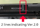 |
Receiver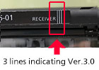 |
| Side nameplate | Receiver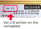 |
Receiver |
■Communication module SF4D-TM1
| Production lot | manufactured before November 2019 | manufactured after December 2019 |
|---|---|---|
| Version of main body | - | Ver. 2.0 |
| Communication module SF4D-TM1 |
 |
 |
| Setting software Configurator Light Curtain |
Version info. Ver.1.3.0 |
Version info. Ver.1.4.0 |
Description and function of each part
|
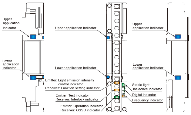
Emitter / receiver common
| Designation | Function | ||||
|---|---|---|---|---|---|
| Line synchronization | Optical synchronization | ||||
| Receiver | Emitter | Receiver | Emitter | ||
| Upper application indicator (Blue / Green / Red / Orange) |
When beam axis adjustment mode is set |
All beams received [Control output (OSSD 1, OSSD 2) ON]: Lights blue Top beam received: Lights red, Top beam blocked: Turns OFF |
Turns OFF | ||
| When application mode is set |
When application indicator input 1 is ON: Lights green When application indicator input 2 is ON: Lights red When application indicator input 1 / 2 are ON: Lights orange When application indicator input 1 / 2 are OFF: Turns OFF |
Turns OFF | |||
| Lower application indicator (Blue / Green / Red / Orange) |
When beam axis adjustment mode is set |
All beams received [Control output (OSSD 1, OSSD 2) ON]: Lights blue Bottom beam received: Lights red, Bottom beam blocked: Turns OFF |
Turns OFF | ||
| When application mode is set |
When application indicator input 1 is ON: Lights green When application indicator input 2 is ON: Lights red When application indicator input 1 / 2 are ON: Lights orange When application indicator input 1 / 2 are OFF: Turns OFF |
Turns OFF | |||
| Stable light incidence indicator (Green / Orange) |
When light reception is stable: Lights green When light reception is unstable: Lights orange When light is blocked: Turns OFF |
Turns OFF | |||
| Digital indicator (Green / Yellow) |
Light receiving intensity (Green) |
Incident light level 3: Lights green " ", ",Incident light level 2: Lights green "  " "Incident light level 1: Lights green "  ", ",When light is blocked: Turns OFF |
Turns OFF | ||
| Error (Yellow) | Normal operation: Turns OFF, Error: Yellow number blinks or lights " " " |
||||
| Polarity (Yellow) | When PNP output is set: Lights yellow " " (only during startup) " (only during startup)When NPN output is set: Lights yellow "  " (only during startup) " (only during startup) |
||||
| Frequency indicator (Orange) | - | When frequency 1 is set: Lights orange " " "When frequency 2 is set: Lights orange "  " " |
|||
Emitter
| Designation (Note 1) |
Function | |
|---|---|---|
| Line synchronization | Optical synchronization | |
| Light emission intensity control indicator (Orange) [CTRL] | Short mode: Turns OFF, Long mode: Lights orange | |
| Test indicator (Orange) [TEST] | During test: Lights orang, Normal operation: Turns OFF | |
| Operation indicator (Green / Red) [OP] | Control output (OSSD 1 / 2) ON: Lights green Control output (OSSD 1 / 2) OFF: Lights red |
Normal operation: Lights green Error: Lights red |
Receiver
| Designation (Note 1) |
Function | |
|---|---|---|
| Line synchronization | Optical synchronization | |
| Function setting indicator (Orange) [FUNC] | When communication module is connected: Blinks orange, When blanking function or parallel connection is used: Lights orange (Note 2) | |
| Interlock indicator (Yellow) [LOCK] | Interlock activated: Lights yellow, All other times: Turns OFF | |
| OSSD indicator (Green / Red) [OSSD] | Control output (OSSD 1 / 2) ON: Lights green Control output (OSSD 1 / 2) OFF: Lights red |
|
Notes:
| 1) | Designations in brackets [ ] are names that are indicated on the device. |
|---|---|
| 2) | For the details of blanking function and parallel connection, refer to the instruction manual. |
- When this device is used in the "PSDI mode", an appropriate control circuit must be configured between this device and the machinery. For details, be sure to refer to the standards or regulations applicable in each region or country.
- Do not use SF4D-□ as a safety device for a press in Japan. For presses and shearing machines (paper cutting machines) in Japan, use SF4D-□-01.
- Do no use SF4D-□-01 as a safety device for a press in South Korea.
- To use this product in the U.S.A., refer to OSHA 1910. 212 and OSHA 1910. 217 for installation, and in Europe, refer to EN ISO 13855 as well. Observe your national and local requirements before installing this product.
| ・ | This web site is a guide to select a suitable product. Be sure to read instruction manual attached to the product prior to its use. |
|---|
- Make sure to carry out the test run before regular operation.
- This safety system is for use only on machinery in which the dangerous parts can be stopped immediately, either by an emergency stop unit or by disconnecting the power supply. Do not use this system with machinery which cannot be stopped at any point in its operation cycle.
When using SF4D-□-01 as a safety device for a press or shearing machine (paper cutting machine) in Japan
- Abide by the Standards for Power Press Structures, the Standards for the Structures of Safety Devices for Presses or Shearing Machines (Paper Cutting Machines) and the Guidelines on Management of Safety Devices for Presses announced by the Japanese Ministry of Health, Labour and Welfare.
- Be sure to install the protective tube, SFPD-A10 (tube length: 10 m 32.808 ft) (optional), to the cables.
About machines for which SF4D-□-01 is used
- When using SF4D-□-01 as a safety device for a press or shearing machine (paper cutting machine) in Japan, make sure that the press or shearing machine (paper cutting machine) satisfies the following specification requirements. Do not use SF4D-□-01 if the machine does not meet the specification requirements.
Press machine
| Item | Specifications |
|---|---|
| Machine type | Press equipped with immediate stopping mechanism and restart prevention mechanism |
| Pressing capacity | 50,000 kN or less |
| Immediate stopping time | 500 ms or less |
| Stroke length | Within (Protective height – Die height) |
| Die size | Within bolster width |
Shearing machine (paper cutting machine)
| Item | Specifications |
|---|---|
| Machine type | Shearing machine (paper cutting machine) equipped with immediate stopping mechanism and restart prevention mechanism |
| Cutting thickness | 200 mm 7.874 in or less |
| Cutting width | 5,000 mm 196.850 in or less |
| Cutter length | 5,500 mm 216.535 in or less |
Others
- This device has been developed / produced for industrial use only.
- Do not use during the initial transient time (2 sec.) after the power supply is switched on.
- Avoid dust, dirt and steam.
- Take care that the safety light curtain does not come in direct contact with water, oil, grease, or organic solvents, such as, thinner, etc.
- Take care that the safety light curtain is not directly exposed to fluorescent light from a rapid-starter lamp or a high frequency lighting device, as it may affect the sensing performance.
- Do not use this product with mobile equipment such as an automated guided vehicle (AGV).
Communication module
- The use of the communication module, SF4D‑TM1 (optional), enables setting of various functions of the device.
(Note that settings cannot be changed when SF4D-□-01 is used.)
Details related to the safety distance, such as the minimum size of detectable objects, varies for some of the functions. When making individual settings, calculate the safety distance and provide a space greater than the safety distance when setting up the device. Unless a sufficient space is provided, the machine will not stop before the dangerous parts of the machine is touched and death or serious injury can occur.
| ・ | For the details of function settings made using the SF4D-TM1 communication module (optional), see the manual for the communication module. |
|---|
Corner mirror
- The corner mirror has not received type examination by the Ministry of Health, Labour and Welfare; therefore, it cannot be used for presses or shearing machines (paper cutting machines) in Japan.
- Be sure to carry out maintenance while referring to the instruction manual for the safety light curtain SF4D series.
- Do not use if dirt, water, or oil, etc. is attached to the reflective surface of this product. Appropriate sensing range may not be maintained due to diffusion or refraction.
- Make sure that you have read the instruction manual for the corner mirror thoroughly before setting up the corner mirrors and safety light curtains, and follow the instructions given. If the equipment is not set up correctly as stipulated in the instruction manual, incident light errors may result in unexpected situations which may result in serious injury or death.
- Please download the instruction manuals from our website.
- Safety light curtain SF4D series cannot be used as a retroreflective type. Avoid installing the safety light curtain as a retroreflective type when this product is applied.
- The mirror part of this product is made of glass. Note that if it is broken, the glass shards may fly apart.
- Do not use if crack or breakage appears on the reflective surface of this product. Proper sensing range may not be maintained due to diffusion or refraction. If crack or breakage appears on the reflective surface of this product, replace the product.
- When adjusting beam channels with a laser alignment tool, etc., take sufficient care that the laser beam reflected by this product does not enter the eyes.
- Failure to follow the above items may result in death or serious injury.
IO-Link communication unit
- Do not use the IO-Link data for safety control.
- This product cannot be used to directly enter settings from the IO-Link master unit to a safety light curtain using IO-Link communication.
- Safety light curtain setting information copy function is a function assuming maintenance of safety light curtain. Please use only when writing the safety light curtain before replacement to the light curtain after replacement. If you write to non-replacement parts, it may not operate properly.
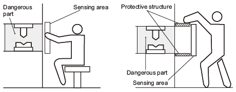
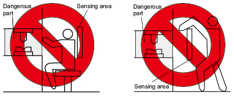
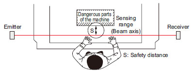
Sensing area
- Make sure to install this product such that any part of the human body must pass through its sensing area in order to reach the dangerous parts of the machinery. If the human body is not detected, there is a danger of serious injury or death.
- Do not use any reflective type or retroreflective type arrangement.
- Multiple receivers (emitters) cannot be connected for use with a single emitter (receiver).
|
|
Safety distance
- Calculate the safety distance correctly, and always maintain a distance which is equal to or greater than the safety distance, between the sensing area of this safety light curtain and the dangerous parts of the machinery.
(Please check the latest standards for the equation.) If the safety distance is miscalculated or if sufficient distance is not maintained, there is a danger of serious injury or death. - Before designing the system, refer to the relevant standards of the region where this device is to be used and then install this device.
|
- The sizes of the minimum sensing objects for this device vary depending on whether or not the floating blanking function is being used.
Calculate the safety distance with the proper size of the minimum sensing object and appropriate equation.
Size of minimum sensing object when applying floating blanking function
Min. sensing object when applying floating blanking function Not set Setting (Note) 1beam
channel2beam
channels3beam
channels4beam
channels5beam
channelsSF4D-F□ ø14 mm
ø0.551 inø24 mm
ø0.945 inø34 mm
ø1.339 inø44 mm
ø1.732 inø54 mm
ø2.126 inø64 mm
ø2.520 inSF4D-H□ ø25 mm
ø0.984 inø45 mm
ø1.772 inø65 mm
ø2.559 inø85 mm
ø3.346 inø105 mm
ø4.134 inø125 mm
ø4.921 inSF4D-A□ ø45 mm
ø1.772 inø85 mm
ø3.346 inø125 mm
ø4.921 inø165 mm
ø6.496 inø205 mm
ø8.071 inø245 mm
ø9.646 inNote: When SF4D-□-01 is used, the floating blanking function cannot be used.
- The safety distance is calculated using the equations given on the following pages when a person moves perpendicularly (normal intrusion) into the sensing area of the device.
If the intrusion direction is not perpendicular, always check the related standards (regional, machine standards, etc.)
| For use based on EN ISO 13855 / ISO 13855 / JIS B 9715 |
For intrusion perpendicular to the sensing area
<When the minimum sensing object is ø40 mm ø1.575 in or less>
• Equation (1) S = K × T + C
| S: | Safety distance (mm) Minimum required distance between the sensing area plane and the dangerous part of the machine |
|---|---|
| K: | Intrusion speed of person or object (mm/sec.) Normally 2,000 (mm/sec.) is used. |
| T: | Response time of overall system T = Tm + TSF4D Tm: Maximum response time of machine (sec.) TSF4D: Response time of device (sec.) |
| C: | Additional distance calculated from the minimum sensing object of the device (mm) The value of C cannot be less than 0. C = 8 × (d − 14) d: Diameter of minimum sensing object (mm) |
| ・ | When calculating the safety distance S, the following five cases must be considered. First calculate using K = 2,000 (mm/sec.) in the above equation. Consider these three cases for the result: 1) S < 100, 2) 100 ≤ S ≤ 500, and 3) S > 500. If the result of the calculation is 3) S > 500, calculate again using K = 1,600 (mm/sec.). Consider these two cases for the result: 4) S ≤500 and 5) S > 500. For details, refer to the manual. |
|---|---|
| ・ | When the device is used in "PSDI mode", an appropriate safety distance S must be calculated. For details, refer to the standards and regulations that apply in your region or country. |
<When the minimum sensing object is greater than ø40 mm ø1.575 in>
• Equation S = K × T + C
| S: | Safety distance (mm) Minimum required distance between the sensing area plane and the nearest dangerous part of the machine |
|---|---|
| K: | Intrusion speed of person or object (mm/sec.) Normally 1,600 (mm/sec.) is used. |
| T: | Overall response time of system T = Tm + TSF4D Tm: Maximum response time of machine (sec.) TSF4D: Response time of device (sec.) |
| C: | Additional distance calculated from the minimum sensing object of the device (mm) C = 850 (mm) (Constant) |
BY EMAIL
- U.S.A.
- +1-800-344-2112
- Europe
- +49-89-45354-1000
- China
- +86-10-59255988
- Singapore
- +65-6299-9181


Requests to customers (Automation Control Components & Industrial Device) [Excluding specific product]
Requests to customers (Automation Control Components & Industrial Device) [For specific product]
Requests to customers (FA Sensors & Components [Excluding motors])
Requests to customers (Dedicated to industrial motors)
- COMPONENTS & DEVICES
- FA SENSORS & COMPONENTS
- Fiber Sensors
- Photoelectric Sensors / Laser Sensors
- Micro Photoelectric Sensors
- Light Curtains / Safety Components
- Area Sensors
- Inductive Proximity Sensors
- Particular Use Sensors
- Sensor Options
- Wire-Saving Systems
- Programmable Controllers / Interface Terminal
- Human Machine Interface
- Pressure Sensors / Flow Sensors
- Measurement Sensors
- Static Control Devices
- Laser Markers / 2D Code Readers
- Machine Vision System
- Energy Management Solutions
- Timers / Counters / FA Components
- MOTORS
![]()