【Notification of Manufacturer Change for Panasonic Industrial Devices SUNX Products and Panasonic Industrial Devices SUNX Tatsuno Products】
From April 1, 2024, the terms "Panasonic Industrial Devices SUNX Co., Ltd." and "Panasonic Industrial Devices SUNX Tatsuno Co., Ltd."
in this page and in the manuals and other documents to be downloaded will all be replaced with "Panasonic Industry Co., Ltd." and applied accordingly.
Pulse AC Method Area Ionizer ER-X
I/O Circuit and Wiring diagrams
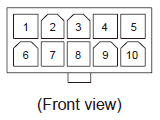
New-type controller (produced from April 2014 on)
Power connector pin arrangement |
 |
|
| Housing: |
5569-10A
[Manufactured by Molex] |
Terminal
No. |
Terminal
name |
Color
code |
| 1 |
0 V |
Blue |
| 2 |
COM(-) |
- |
| 3 |
Discharge
control input |
Pink |
| 4 |
COM(OUT) |
Violet |
| 5 |
F.G. terminal |
Green / Yellow |
| 6 |
24 V |
Brown |
| 7 |
COM(+) |
- |
| 8 |
COM(IN) |
White |
| 9 |
Alarm output |
Orange |
| 10 |
Error output |
Black |
| Note: |
Color code refers to cable colors of an optional power supply cable. |
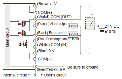
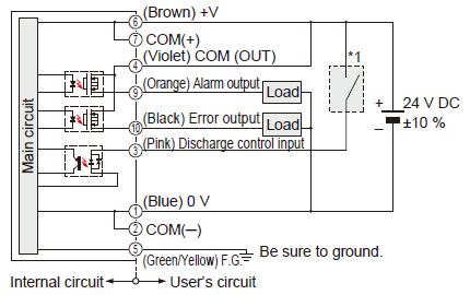
When connecting the output to negative common |
 |
|
*1 |
 |
|
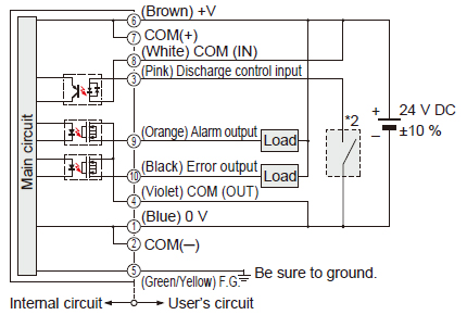
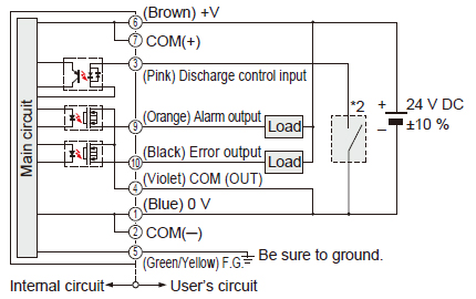
When connecting the output to positive common |
 |
|
*2 |
 |
|
Notes:
| 1) |
Be sure to ground the F.G. terminal. If F.G. terminal is not connected properly, it may cause electric shock.
In the case of ER-X001, the head mounting bracket and F.G. terminal are internally connected. |
| 2) |
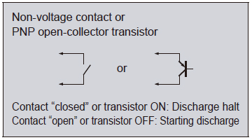
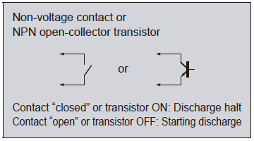
To stop discharge, turn ON the discharge control input for 20 ms or longer. To start discharge, turn OFF (open) the discharge control input. Discharge will start in 20 ms. |
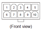
Previous-type controller (produced before March 2014)
Power connector pin arrangement |
 |
|
| Housing: |
5569-10A
[Manufactured by Molex] |
Terminal
No. |
Terminal
name |
Color
code |
| 1 |
0 V |
Blue |
| 2 |
COM(-) |
- |
| 3 |
Discharge
control input |
Pink |
| 4 |
COM(OUT) |
Violet |
| 5 |
F.G. terminal |
Green / Yellow |
| 6 |
24 V |
Brown |
| 7 |
COM(+) |
- |
| 8 |
- |
White |
| 9 |
Alarm output |
Orange |
| 10 |
Error output |
Black |
| Note: |
Color code refers to cable colors of an optional power supply cable. |
When connecting the output to negative common |
 |
|
*1 |
 |
|
When connecting the output to positive common |
 |
|
*2 |
 |
|
Notes:
| 1) |
Be sure to ground the F.G. terminal. If F.G. terminal is not connected properly, it may cause electric shock. |
| 2) |
To stop discharge, turn ON the discharge control input for 20 ms or longer. To start discharge, turn OFF (open) the discharge control input. Discharge will start in 20 ms. |
Return to top
Return to top

 Business
> Industrial Devices
> Automation Controls Top
> FA Sensors & Components
> Static Control Devices
> Static Control Devices
> Pulse AC Method Area Ionizer ER-X
> I/O Circuit and Wiring diagrams
Business
> Industrial Devices
> Automation Controls Top
> FA Sensors & Components
> Static Control Devices
> Static Control Devices
> Pulse AC Method Area Ionizer ER-X
> I/O Circuit and Wiring diagrams


