
 Business
> Industrial Devices
> Automation Controls Top
> FA Sensors & Components
> Sensors
> Photoelectric Sensors / Laser Sensors
> Robust Photoelectric Sensor RX(Discontinued Products)
> Specifications
Business
> Industrial Devices
> Automation Controls Top
> FA Sensors & Components
> Sensors
> Photoelectric Sensors / Laser Sensors
> Robust Photoelectric Sensor RX(Discontinued Products)
> Specifications
Robust Photoelectric Sensor RX (Discontinued Products)
|
We are sorry, the products have been discontinued. Please refer to the details of the discontinued products and the recommended substitutes list below.
|
|
Specifications
Standard type
| Type | Thru-beam | ||
|---|---|---|---|
| Infrared | |||
| Long sensing range |
|||
| Model No. | RX-M10 | RX-M50 | |
| CE marking directive compliance | EMC Directive, RoHS Directive | ||
| Sensing range | 10 m 32.808 ft |
50 m 164.042 ft |
|
| Sensing object | φ10 mm 0.394 in or more opaque object (Note 4) | ||
| Hysteresis | - | ||
| Repeatability (perpendicular to sensing axis) |
0.5 mm 0.020 in or less | ||
| Supply voltage | 12 to 24 V DC ±10 % Ripple P-P 10 % or less | ||
| Current consumption | Emitter: 20 mA or less (RX-M50: 25 mA or less), Receiver: 25 mA or less |
||
| Sensing output | NPN open-collector transistor • Maximum sink current: 100 mA • Applied voltage: 30 V DC or less (between sensing output and 0 V) • Residual voltage: 2 V or less (at 100 mA sink current), 1 V or less (at 16 mA sink current) |
||
| Utilization category | DC-12 or DC-13 | ||
| Output operation | Switchable either Light-ON or Dark-ON | ||
| Short-circuit protection |
Incorporated | ||
| Self-diagnosis output | NPN open-collector transistor • Maximum sink current: 50 mA • Applied voltage: 30 V DC or less (between self-diagnosis output and 0 V) • Residual voltage: 1.5 V or less (at 50 mA sink current), 1 V or less (at 16 mA sink current) |
||
| Output operation | ON under unstable sensing condition | ||
| Short-circuit protection |
- | ||
| Response time | 1 ms or less | ||
| Test input (emission halt) function |
Incorporated | ||
| Operation indicator | Red LED (lights up when the sensing output is ON) | ||
| Stability indicator | Green LED (lights up under stable light received condition or stable dark condition) |
||
| Emitting indicator | Red LED (lights up during beam emission) | ||
| Sensitivity adjuster | Continuously variable adjuster | ||
| Automatic interference prevention function |
- | ||
| Pollution degree | 3 (Industrial environmrnt) | ||
| Protection | IP67 (IEC) | ||
| Ambient temperature | –25 to +60 ℃ –13 to +140 ℉ (No dew condensation or icing allowed), Storage: –30 to +70 ℃ –22 to +158 ℉ |
||
| Ambient humidity | 35 to 85 % RH, Storage: 35 to 85 % RH | ||
| Ambient illuminance | Incandescent light: 3,500 Lx or less at the light-receiving face | ||
| Voltage withstandability |
1,000 V AC for one min. between all supply terminals connected together and enclosure | ||
| Insulation resistance | 20 MΩ, or more, with 250 V DC megger between all supply terminals connected together and enclosure | ||
| Vibration resistance | 10 to 500 Hz frequency, 1.5 mm 0.059 in double amplitude (10 G max.) in X, Y and Z directions for two hours each | ||
| Shock resistance | 500 m/s2 acceleration (50 G approx.) in X, Y and Z directions three times each | ||
| Emitting element (modulated) |
Infrared LED | ||
| Peak emission wavelength |
880 nm 0.035 mil |
||
| Material | Enclosure: Die-cast zinc alloy, Indicator cover: Polyethersulphone, Lens: Polycarbonate |
||
| Cable | Emitter: 0.15 mm2 3-core oil, heat and cold resistant cabtyre cable, 2 m 6.562 ft long Receiver: 0.15 mm2 4-core oil, heat and cold resistant cabtyre cable, 2 m 6.562 ft long |
||
| Cable extension | Extension up to total 100 m 328.084 ft is possible with 0.3 mm2, or more, cable (thru-beam type: both emitter and receiver). |
||
| Net weight | Emitter: 70 g approx. (RX-M50: 75 g approx.) Receiver: 70 g approx. (RX-M50: 75 g approx.) |
||
| Accessories | MS-RX-1 (Sensor mounting bracket) : 1 set for emitter and receiver Adjusting screwdriver : 1 pc. |
||
| Type | Retroreflective | Diffuse reflective | |
|---|---|---|---|
| Infrared (Long sensing range) |
Infrared | ||
| Model No. | RX-RVM5 | RX-D700 | |
| CE marking directive compliance | EMC Directive, RoHS Directive | ||
| Sensing range | 0.1 to 5 m 0.328 to 16.404 ft (Note 2) |
700 mm 27.559 in (Note 3) |
|
| Sensing object | φ50 mm φ1.969 in or more opaque, or translucent object (Note 2, 5) |
Opaque, translucent or transparent object (Note 5) |
|
| Hysteresis | - | 15 % or less of operation distance (Note 3) |
|
| Repeatability (perpendicular to sensing axis) |
1 mm 0.039 in or less | 0.5 mm 0.020 in or less | |
| Supply voltage | 12 to 24 V DC ±10 % Ripple P-P 10 % or less | ||
| Current consumption | 40 mA or less | ||
| Sensing output | NPN open-collector transistor • Maximum sink current: 100 mA • Applied voltage: 30 V DC or less (between sensing output and 0 V) • Residual voltage: 2 V or less (at 100 mA sink current), 1 V or less (at 16 mA sink current) |
||
| Utilization category | DC-12 or DC-13 | ||
| Output operation | Switchable either Light-ON or Dark-ON | ||
| Short-circuit protection |
Incorporated | ||
| Self-diagnosis output | NPN open-collector transistor • Maximum sink current: 50 mA • Applied voltage: 30 V DC or less (between self-diagnosis output and 0 V) • Residual voltage: 1.5 V or less (at 50 mA sink current), 1 V or less (at 16 mA sink current) |
||
| Output operation | ON under unstable sensing condition | ||
| Short-circuit protection |
- | ||
| Response time | 1 ms or less | ||
| Test input (emission halt) function |
Incorporated | ||
| Operation indicator | Red LED (lights up when the sensing output is ON) | ||
| Stability indicator | Green LED (lights up under stable light received condition or stable dark condition) |
||
| Emitting indicator | - | ||
| Sensitivity adjuster | Continuously variable adjuster | ||
| Automatic interference prevention function |
Incorporated (Two units of sensors can be mounted close together.) | ||
| Pollution degree | 3 (Industrial environmrnt) | ||
| Protection | IP67 (IEC) | ||
| Ambient temperature | –25 to +60 ℃ –13 to +140 ℉ (No dew condensation or icing allowed), Storage: –30 to +70 ℃ –22 to +158 ℉ |
||
| Ambient humidity | 35 to 85 % RH, Storage: 35 to 85 % RH | ||
| Ambient illuminance | Incandescent light: 3,500 Lx or less at the light-receiving face | ||
| Voltage withstandability |
1,000 V AC for one min. between all supply terminals connected together and enclosure | ||
| Insulation resistance | 20 MΩ, or more, with 250 V DC megger between all supply terminals connected together and enclosure | ||
| Vibration resistance | 10 to 500 Hz frequency, 1.5 mm 0.059 in double amplitude (10 G max.) in X, Y and Z directions for two hours each | ||
| Shock resistance | 500 m/s2 acceleration (50 G approx.) in X, Y and Z directions three times each | ||
| Emitting element (modulated) |
Infrared LED | ||
| Peak emission wavelength |
880 nm 0.035 mil |
||
| Material | Enclosure: Die-cast zinc alloy, Indicator cover: Polyethersulphone, Lens: Polycarbonate (Retroreflective type: Acrylic) |
||
| Cable | 0.15 mm2 5-core oil, heat and cold resistant cabtyre cable, 2 m 6.562 ft long |
||
| Cable extension | Extension up to total 100 m 328.084 ft is possible with 0.3 mm2, or more, cable | ||
| Net weight | 75 g approx. | ||
| Accessories | MS-RX-1 (Sensor mounting bracket): 1 set RF-230 (Reflector): 1 pc. Adjusting screwdriver: 1 pc. |
MS-RX-1 (Sensor mounting bracket): 1 set Adjusting screwdriver: 1 pc. |
|
Notes:
| 1) | Where measurement conditions have not been specified precisely, the conditions used were an ambient temperature of +23 ℃ +73.4 ℉. |
|---|---|
| 2) | The sensing range and the sensing object for the retroreflective type sensor are specified for the RF-230 reflector. Further, the sensing range of RX-PRVM3 and RX-RVM5 is the possible setting range for the reflector. The sensor can detect an object less than 0.1 m 0.328 ft away.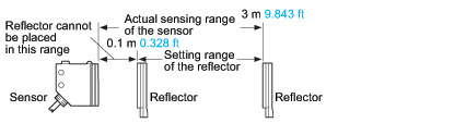 |
| 3) | The sensing range and the hysteresis of the diffuse reflective type sensor are specified for white non-glossy paper (200 x 200 mm 7.874 x 7.874 in) as the object. |
| 4) | If slit masks (optional) are fitted on RX-M10, an object of 0.5 x 5 mm 0.020 x 0.197 in can be detected. |
| 5) | Make sure to confirm detection with an actual sensor before use. |
| Type | Thru-beam | ||
|---|---|---|---|
| Red | Green | ||
| Model No. | RX-M2R | RX-500G | |
| CE marking directive compliance | EMC Directive, RoHS Directive | ||
| Sensing range | 2 m 6.562 ft |
500 mm 19.685 in |
|
| Sensing object | φ10 mm 0.394 in or more opaque object (Note 4) | ||
| Hysteresis | - | ||
| Repeatability (perpendicular to sensing axis) |
0.5 mm 0.020 in or less | ||
| Supply voltage | 12 to 24 V DC ±10 % Ripple P-P 10 % or less | ||
| Current consumption | Emitter: 20 mA or less (RX-M50: 25 mA or less), Receiver: 25 mA or less |
||
| Sensing output | NPN open-collector transistor • Maximum sink current: 100 mA • Applied voltage: 30 V DC or less (between sensing output and 0 V) • Residual voltage: 2 V or less (at 100 mA sink current), 1 V or less (at 16 mA sink current) |
||
| Utilization category | DC-12 or DC-13 | ||
| Output operation | Switchable either Light-ON or Dark-ON | ||
| Short-circuit protection |
Incorporated | ||
| Self-diagnosis output | NPN open-collector transistor • Maximum sink current: 50 mA • Applied voltage: 30 V DC or less (between self-diagnosis output and 0 V) • Residual voltage: 1.5 V or less (at 50 mA sink current), 1 V or less (at 16 mA sink current) |
||
| Output operation | ON under unstable sensing condition | ||
| Short-circuit protection |
- | ||
| Response time | 1 ms or less | ||
| Test input (emission halt) function |
Incorporated | ||
| Operation indicator | Red LED (lights up when the sensing output is ON) | ||
| Stability indicator | Green LED (lights up under stable light received condition or stable dark condition) |
||
| Emitting indicator | Red LED (lights up during beam emission) | ||
| Sensitivity adjuster | Continuously variable adjuster | ||
| Automatic interference prevention function |
- | ||
| Pollution degree | 3 (Industrial environmrnt) | ||
| Protection | IP67 (IEC) | ||
| Ambient temperature | –25 to +60 ℃ –13 to +140 ℉ (No dew condensation or icing allowed), Storage: –30 to +70 ℃ –22 to +158 ℉ |
||
| Ambient humidity | 35 to 85 % RH, Storage: 35 to 85 % RH | ||
| Ambient illuminance | Incandescent light: 3,500 Lx or less at the light-receiving face | ||
| Voltage withstandability |
1,000 V AC for one min. between all supply terminals connected together and enclosure | ||
| Insulation resistance | 20 MΩ, or more, with 250 V DC megger between all supply terminals connected together and enclosure | ||
| Vibration resistance | 10 to 500 Hz frequency, 1.5 mm 0.059 in double amplitude (10 G max.) in X, Y and Z directions for two hours each | ||
| Shock resistance | 500 m/s2 acceleration (50 G approx.) in X, Y and Z directions three times each | ||
| Emitting element (modulated) |
Red LED | Green LED | |
| Peak emission wavelength |
660 nm 0.026 mil |
570 nm 0.022 mil |
|
| Material | Enclosure: Die-cast zinc alloy, Indicator cover: Polyethersulphone, Lens: Polycarbonate |
||
| Cable | Emitter: 0.15 mm2 3-core oil, heat and cold resistant cabtyre cable, 2 m 6.562 ft long Receiver: 0.15 mm2 4-core oil, heat and cold resistant cabtyre cable, 2 m 6.562 ft long |
||
| Cable extension | Extension up to total 100 m 328.084 ft is possible with 0.3 mm2, or more, cable (thru-beam type: both emitter and receiver). |
||
| Net weight | Emitter: 70 g approx. (RX-M50: 75 g approx.) Receiver: 70 g approx. (RX-M50: 75 g approx.) |
||
| Accessories | MS-RX-1 (Sensor mounting bracket) : 1 set for emitter and receiver Adjusting screwdriver : 1 pc. |
||
| Type | Retroreflective | Diffuse reflective | |
|---|---|---|---|
| Red (with polarizing filters) |
GreReden | ||
| Model No. | RX-PRVM3 | RX-D200R | |
| CE marking directive compliance | EMC Directive, RoHS Directive | ||
| Sensing range | 0.1 to 3 m 0.328 to 9.843 ft (Note 2) |
200 mm 7.874 in (Note 3) |
|
| Sensing object | φ50 mm φ1.969 in or more opaque, translucent or specular object (Note 2, 4) |
Opaque, translucent or transparent object (Note 4) |
|
| Hysteresis | - | 15 % or less of operation distance (Note 3) |
|
| Repeatability (perpendicular to sensing axis) |
1 mm 0.039 in or less | 0.5 mm 0.020 in or less | |
| Supply voltage | 12 to 24 V DC ±10 % Ripple P-P 10 % or less | ||
| Current consumption | 40 mA or less | ||
| Sensing output | NPN open-collector transistor • Maximum sink current: 100 mA • Applied voltage: 30 V DC or less (between sensing output and 0 V) • Residual voltage: 2 V or less (at 100 mA sink current), 1 V or less (at 16 mA sink current) |
||
| Utilization category | DC-12 or DC-13 | ||
| Output operation | Switchable either Light-ON or Dark-ON | ||
| Short-circuit protection |
Incorporated | ||
| Self-diagnosis output | NPN open-collector transistor • Maximum sink current: 50 mA • Applied voltage: 30 V DC or less (between self-diagnosis output and 0 V) • Residual voltage: 1.5 V or less (at 50 mA sink current), 1 V or less (at 16 mA sink current) |
||
| Output operation | ON under unstable sensing condition | ||
| Short-circuit protection |
- | ||
| Response time | 1 ms or less | ||
| Test input (emission halt) function |
Incorporated | ||
| Operation indicator | Red LED (lights up when the sensing output is ON) | ||
| Stability indicator | Green LED (lights up under stable light received condition or stable dark condition) |
||
| Emitting indicator | - | ||
| Sensitivity adjuster | Continuously variable adjuster | ||
| Automatic interference prevention function |
Incorporated (Two units of sensors can be mounted close together.) | ||
| Pollution degree | 3 (Industrial environmrnt) | ||
| Protection | IP67 (IEC) | ||
| Ambient temperature | –25 to +60 ℃ –13 to +140 ℉ (No dew condensation or icing allowed), Storage: –30 to +70 ℃ –22 to +158 ℉ |
||
| Ambient humidity | 35 to 85 % RH, Storage: 35 to 85 % RH | ||
| Ambient illuminance | Incandescent light: 3,500 Lx or less at the light-receiving face | ||
| Voltage withstandability |
1,000 V AC for one min. between all supply terminals connected together and enclosure | ||
| Insulation resistance | 20 MΩ, or more, with 250 V DC megger between all supply terminals connected together and enclosure | ||
| Vibration resistance | 10 to 500 Hz frequency, 1.5 mm 0.059 in double amplitude (10 G max.) in X, Y and Z directions for two hours each | ||
| Shock resistance | 500 m/s2 acceleration (50 G approx.) in X, Y and Z directions three times each | ||
| Emitting element (modulated) |
Red LED | Red LED | |
| Peak emission wavelength |
680 nm 0.027 mil |
680 nm 0.027 mil |
|
| Material | Enclosure: Die-cast zinc alloy, Indicator cover: Polyethersulphone, Lens: Polycarbonate (Retroreflective type: Acrylic) |
||
| Cable | 0.15 mm2 5-core oil, heat and cold resistant cabtyre cable, 2 m 6.562 ft long |
||
| Cable extension | Extension up to total 100 m 328.084 ft is possible with 0.3 mm2, or more, cable | ||
| Net weight | 75 g approx. | ||
| Accessories | MS-RX-1 (Sensor mounting bracket): 1 set RF-230 (Reflector): 1 pc. Adjusting screwdriver: 1 pc. |
MS-RX-1 (Sensor mounting bracket): 1 set Adjusting screwdriver: 1 pc. |
|
Notes:
| 1) | Where measurement conditions have not been specified precisely, the conditions used were an ambient temperature of +23 ℃ +73.4 ℉. |
|---|---|
| 2) | The sensing range and the sensing object for the retroreflective type sensor are specified for the RF-230 reflector. Further, the sensing range of RX-PRVM3 and RX-RVM5 is the possible setting range for the reflector. The sensor can detect an object less than 0.1 m 0.328 ft away. |
| 3) | The sensing range and the hysteresis of the diffuse reflective type sensor are specified for white non-glossy paper (200 x 200 mm 7.874 x 7.874 in) as the object. |
| 4) | Make sure to confirm detection with an actual sensor before use. |
DC 2-wire type
| Type | Thru-beam | Retroreflective (with polarizing filters) |
Diffuse reflective | |
|---|---|---|---|---|
| Model No. | RX2-M5 | RX2-PRVM2 | RX2-D300 | |
| Sensing range | 5 m 16.404 ft |
0.1 to 2 m 0.328 to 6.562 ft (Note 2) |
300 mm 11.811 in (Note 3) |
|
| Sensing object | φ10 mm φ0.394 in or more opaque object (Note 4) |
φ50 mm φ1.969 in or more opaque, translucent or specular object (Note 2, 5) |
Opaque, translucent or transparent object (Note 5) |
|
| Hysteresis | - | - | 15 % or less of operation distance (Note 3) |
|
| Repeatability (perpendicular to sensing axis) |
0.5 mm 0.020 in or less | 1 mm 0.039 in or less | 0.5 mm 0.020 in or less | |
| Supply voltage | 12 to 24 V DC ±10 % Ripple P-P 10 % or less | |||
| Current consumption | Emitter: 8 mA or less, Receiver: 0.8 mA or less (Note 6) |
1 mA or less (Note 6) |
||
| Sensing output | Non contact DC 2-wire type • Load current: 5 to 100 mA • Residual voltage: 4 V or less (Note 7) |
|||
| Output operation | Switchable either Light-ON or Dark-ON | |||
| Short-circuit protection |
Incorporated | |||
| Response time | 3 ms or less | |||
| Operation indicator | Red LED (lights up when the output is ON) | |||
| Stability indicator | Green LED (Light-ON mode: lights up under stable light received condition Dark-ON mode: lights up under stable dark condition) |
|||
| Emitting indicator | Red LED (lights up during beam emission) |
- | ||
| Sensitivity adjuster | Continuously variable adjuster | |||
| Protection | IP67 (IEC) | |||
| Ambient temperature | –20 to +60 ℃ –4 to +140 ℉ (No dew condensation or icing allowed), Storage: –30 to +70 ℃ –22 to +158 ℉ |
|||
| Ambient humidity | 35 to 85 % RH, Storage: 35 to 85 % RH | |||
| Ambient illuminance | Incandescent light: 3,500 Lx or less at the light-receiving face | |||
| Voltage withstandability | 1,000 V AC for one min. between all supply terminals connected together and enclosure | |||
| Insulation resistance | 20 MΩ, or more, with 250 V DC megger between all supply terminals connected together and enclosure | |||
| Vibration resistance | 10 to 500 Hz frequency, 1.5 mm 0.059 in double amplitude (10 G max.) in X, Y and Z directions for two hours each | |||
| Shock resistance | 500 m/s2 acceleration (50 G approx.) in X, Y and Z directions three times each | |||
| Emitting element | Infrared LED (modulated) |
Red LED (modulated) |
Infrared LED (modulated) |
|
| Peak emission wavelength |
880 nm 0.035 mil | 680 nm 0.027 mil | 890 nm 0.035 mil | |
| Material | Enclosure: Die-cast zinc alloy, Indicator cover: Polyethersulphone, Lens: Polycarbonate (RX2-PRVM2: Acrylic) | |||
| Cable | 0.15 mm2 2-core oil, heat and cold resistant cabtyre cable, 2 m 6.562 ft long | |||
| Cable extension | - (Note 7) | |||
| Net weight | Emitter: 70 g approx., Receiver: 70 g approx. |
75 g approx. | 70 g approx. | |
| Accessories | MS-RX-1 (Sensor mounting bracket): 1 set for emitter and receiver Adjusting screwdriver: 1 pc. |
MS-RX-1 (Sensor mounting bracket): 1 set RF-230 (Reflector): 1 pc. Adjusting screwdriver: 1 pc. |
MS-RX-1 (Sensor mounting bracket): 1 set Adjusting screwdriver: 1 pc. |
|
Notes:
| 1) | Where measurement conditions have not been specified precisely, the conditions used were an ambient temperature of +23 ℃ +73.4 ℉. |
|---|---|
| 2) | The sensing range and the sensing object for RX2-PRVM2 are specified for the RF-230 reflector. Further, the sensing range is the possible setting range for the reflector. The sensor can detect an object less than 0.1 m 0.328 ft away.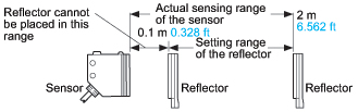 |
| 3) | The sensing range and the hysteresis of RX2-D300 are specified for white non-glossy paper (200 x 200 mm 7.874 x 7.874 in) as the object. |
| 4) | If slit masks (optional) are fitted, an object of 0.5 x 5 mm 0.020 x 0.197 in can be detected. |
| 5) | Make sure to confirm detection with an actual sensor before use. |
| 6) | It is the leakage current when the output is in the OFF state. |
| 7) | When extending the cable, the residual voltage will be increased depending on the type of cable used. Verify the residual voltage when extending the cable. |
Heavy duty type
| Type | Thru-beam | |||
|---|---|---|---|---|
| Cable length 2 m 6.562 ft |
Cable length 3 m 9.843 ft |
Cable length 5 m 16.404 ft |
||
| Model No. | RX4-M5 | RX4-M5-C3 | RX4-M5-C5 | |
| Sensing range | 5 m 16.404 ft | |||
| Sensing object | φ10 mm φ0.394 in or more opaque object | |||
| Repeatability (perpendicular to sensing axis) |
0.5 mm 0.020 in or less | |||
| Supply voltage | 12 to 24 V DC ±10 % Ripple P-P 10 % or less | |||
| Current consumption | Emitter: 20 mA or less, Receiver: 25 mA or less | |||
| Sensing output | NPN open-collector transistor • Maximum sink current: 100 mA • Applied voltage: 30 V DC or less (between sensing output and 0 V) • Residual voltage: 2 V or less (at 100 mA sink current), 1 V or less (at 16 mA sink current) |
|||
| Output operation | Switchable either Light-ON or Dark-ON | |||
| Short-circuit protection |
Incorporated | |||
| Self-diagnosis output | NPN open-collector transistor • Maximum sink current: 50 mA • Applied voltage: 30 V DC or less (between self-diagnosis output and 0 V) • Residual voltage: 1.5 V or less (at 50 mA sink current), 1 V or less (at 16 mA sink current) |
|||
| Output operation | ON under unstable sensing condition | |||
| Short-circuit protection |
- | |||
| Response time | 1 ms or less | |||
| Test input (emission halt) function |
Incorporated | |||
| Operation indicator | Red LED (lights up when the sensing output is ON) | |||
| Stability indicator | Green LED (lights up under stable light received condition or stable dark condition) |
|||
| Emitting indicator | Red LED (lights up during beam emission) | |||
| Sensitivity adjuster | Continuously variable adjuster | |||
| Protection | IP67 (IEC), IP67G | |||
| Ambient temperature | –25 to +60 ℃ –13 to +140 ℉ (No dew condensation or icing allowed), Storage: –30 to +70 ℃ –22 to +158 ℉ |
|||
| Ambient humidity | 35 to 85 % RH, Storage: 35 to 85 % RH | |||
| Ambient illuminance | Incandescent light: 3,500 Lx or less at the light-receiving face | |||
| Voltage withstandability | 1,000 V AC for one min. between all supply terminals connected together and enclosure | |||
| Insulation resistance | 20 MΩ, or more, with 250 V DC megger between all supply terminals connected together and enclosure | |||
| Vibration resistance | 10 to 500 Hz frequency, 1.5 mm 0.059 in double amplitude (10 G max.) in X, Y and Z directions for two hours each | |||
| Shock resistance | 500 m/s2 acceleration (50 G approx.) in X, Y and Z directions three times each | |||
| Emitting element | Infrared LED (Peak emission wavelength: 880 nm 0.035 mil, modulated) | |||
| Material | Enclosure: Die-cast zinc alloy (Fluorine resin coating), Indicator cover: Polyethersulphone, Lens: Polyalylate, Protective tube sheath: Oil resistant PVC |
|||
| Cable | 0.15 mm2 4-core (emitter: 3-core) oil, heat and cold resistant cabtyre cable | |||
| Protective tube length | 1 m 3.281 ft | 2 m 6.562 ft | 4 m 13.123 ft | |
| Cable extension | Extension up to total 100 m 328.084 ft is possible for both emitter and receiver with 0.3 mm2, or more, cable. | |||
| Net weight | Emitter: 175 g approx., Receiver: 175 g approx. |
Emitter: 265 g approx., Receiver: 265 g approx. |
Emitter: 495 g approx., Receiver: 495 g approx. |
|
| Accessories | MS-RX-2 (Sensor mounting bracket): 1 set for emitter and receiver, Adjusting screwdriver: 1 pc. |
|||
Note:
Where measurement conditions have not been specified precisely, the conditions used were an ambient temperature of +23 ℃ +73.4 ℉.
BY EMAIL


Requests to customers (Automation Control Components & Industrial Device) [Excluding specific product]
Requests to customers (Automation Control Components & Industrial Device) [For specific product]
Requests to customers (FA Sensors & Components [Excluding motors])
Requests to customers (Dedicated to industrial motors)
- COMPONENTS & DEVICES
- FA SENSORS & COMPONENTS
- Fiber Sensors
- Photoelectric Sensors / Laser Sensors
- Micro Photoelectric Sensors
- Light Curtains / Safety Components
- Area Sensors
- Inductive Proximity Sensors
- Particular Use Sensors
- Sensor Options
- Wire-Saving Systems
- Programmable Controllers / Interface Terminal
- Human Machine Interface
- Pressure Sensors / Flow Sensors
- Measurement Sensors
- Static Control Devices
- Laser Markers / 2D Code Readers
- Machine Vision System
- Energy Management Solutions
- Timers / Counters / FA Components
- MOTORS
![]()