【Notification of Manufacturer Change for Panasonic Industrial Devices SUNX Products and Panasonic Industrial Devices SUNX Tatsuno Products】
From April 1, 2024, the terms "Panasonic Industrial Devices SUNX Co., Ltd." and "Panasonic Industrial Devices SUNX Tatsuno Co., Ltd."
in this page and in the manuals and other documents to be downloaded will all be replaced with "Panasonic Industry Co., Ltd." and applied accordingly.
Key selector switch SG-D1 (Discontinued Products)
We are sorry, the products have been discontinued. Please refer to the details of the discontinued products and the recommended substitutes list below.
 |
September 30, 2019 |
|
|
Cautions For Use
- In order to avoid electric shock or fire, turn the power off before installation, removal, wire connection,
maintenance, or inspection of the safety switch.
- Use wiring that is appropriate for the applied
voltage and energized current, and tighten terminal screws (M3.5) to the recommended tightening torque (1.0 to 1.3 N・m). Using the switch when the screws are loose will cause it to become extremely
hot, posing the risk of fire.
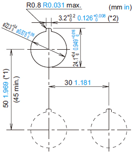
Mounting hole layout / minimum mounting center
|
|
Note:
When using the safety lever lock, determine the vertical spacing(*1) in
consideration of convenience for installing and removing the safety
lever lock. (Recommended vertical spacing: 100 mm 3.937 in or more)
The 3.2+0.20 0.126+0.0080recess(*2) is for preventing rotation and not
necessary when anti-rotation is not used.
|
- The minimum mounting centers are applicable to switches with
one layer of contact blocks (two contact blocks).
When two layers of contact blocks are mounted, determine the minimum mounting centers in consideration of convenience for wiring.
Applicable wiring
(1) The applicable wire size is 2 mm2 maximum. (single wire ø1.6
mm ø0.063 in maximum) One or two wires can be connected.
・Applicable crimping terminal (Unit: mm in) |
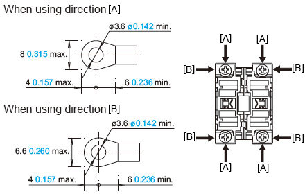 |
| Be sure to use an insulation tube or cover on the crimping part of the crimping terminal to prevent electrical shocks. |
|
・Single wire (Unit: mm in) |
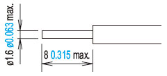 |
| Note: When connecting wires to contact blocks or transformers in the direction [B], keep the insulation stripping length 6.6 mm 0.260 in at the maximum. |
|
(2) Tighten the M3.5 terminal screws to a torque of 1.0 to 1.3 N・m.
Using the lever lock (accessory)
・Please attach the lever lock (yellow) after locking to prevent personnel from forgetting to lock the lock lever.
Return to top
Return to top

 Business
> Industrial Devices
> Automation Controls Top
> FA Sensors & Components
> Sensors
> Light Curtains / Safety Components
> Key selector switch SG-D1(Discontinued Products)
> Cautions For Use
Business
> Industrial Devices
> Automation Controls Top
> FA Sensors & Components
> Sensors
> Light Curtains / Safety Components
> Key selector switch SG-D1(Discontinued Products)
> Cautions For Use