
![]() 企業專屬首頁
> 電子元件/工業用機器
> 制御機器首頁
> FA 感測器/系統
> 檢查‧判別‧測量用感測器
> 檢查‧判別‧測量用感測器
> 對照式數位位移感測器 HG-T
> 品名
> HG-TC101
企業專屬首頁
> 電子元件/工業用機器
> 制御機器首頁
> FA 感測器/系統
> 檢查‧判別‧測量用感測器
> 檢查‧判別‧測量用感測器
> 對照式數位位移感測器 HG-T
> 品名
> HG-TC101
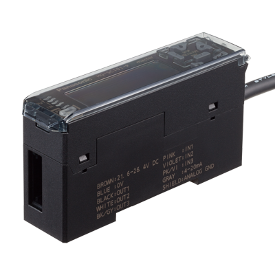
HG-TC101 | 對照式數位位移感測器 HG-T


截至2024年04月30日
為了改善本產品,會有在未事先通知的情況下變更本產品的規格及設計的情況。
詳細規格
| 項目 | 內容 | |||||||||||||
|---|---|---|---|---|---|---|---|---|---|---|---|---|---|---|
| 品名 | HG-TC101 | |||||||||||||
| 型號 | HG-TC101 | |||||||||||||
| Regulatory compliance | CE Marking (EMC Directive, RoHS Directive), UKCA Marking (EMC Regulations, RoHS Regulations) | |||||||||||||
| Pollution degree | 2 | |||||||||||||
| Operating altitude | 2,000 m 6561.68 ft or less (Note) : Do not use or store in an environment that has been pressurized to an air pressure higher than the atmospheric pressure at 0 m. |
|||||||||||||
| Environmental resistance : Protection | IP40(IEC) | |||||||||||||
| Environmental resistance : Ambient temperature | -10 to +50 ℃ +14 to +122 ℉ (No dew condensation or icing allowed) (Note), Storage: -20 to +60 ℃ -4 to +140 ℉ (Note) : When slave units are connected to the master unit, the maximum sink current / source current of control output and ambient temperature vary depending on the number of connected slave units as shown below.
|
|||||||||||||
| Environmental resistance : Ambient humidity | 35 to 85 % RH, Storage: 35 to 85 % RH | |||||||||||||
| Environmental resistance : Voltage withstandability | 1,000 V AC for one minute between all supply terminals connected together and enclosure | |||||||||||||
| Environmental resistance : Insulation resistance | 20 MΩ, or more, with 250 V DC megger between all supply terminals connected together and enclosure | |||||||||||||
| Environmental resistance : Vibration resistance | 10 to 150 Hz frequency, 0.75 mm 0.030 in double amplitude (10 to 58 Hz), Maximum acceleration 49 m/s2 (58 to 150 Hz) in X, Y and Z directions for two hours each | |||||||||||||
| Environmental resistance : Shock resistance | 98m/s2 acceleration (10 G approx.) in X, Y and Z directions five times each | |||||||||||||
| Material | Case: Polycarbonate, Cover: Polycarbonate, Switches: Polyacetal | |||||||||||||
| Cable | 0.2 mm2 2-core (brown and blue lead wires) / 0.15 mm2 7-core composite cable, 2 m 6.562 ft long | |||||||||||||
| Net weight | 140 g approx. | |||||||||||||
| Applicable sensor head | HG-T1010、HG-T1110 | |||||||||||||
| Maximum number of connectable controllers | Up to 15 slave units can be connected to a master unit. (Note) : When connected to a communication unit for digital displacement sensor, up to 14 slave units can be connected per master unit. |
|||||||||||||
| Supply voltage | 24 V DC ±10 %, including ripple 0.5 V (P-P) | |||||||||||||
| Current consumption | 100 mA or less (when sensor head is connected) (Note) : Current consumption does not include analog current output. |
|||||||||||||
| Analogue output : Analog voltage output | •Voltage output range: 1 to 5 V/F.S. (default value) •Linearity: ±0.05 % F.S. •Output when alarm occurs: 5.2 V •Output impedance: 100 Ω max. (Note) : Linearity is a value calculated from digitally measured values at F.S. = 16 mA for current output or F.S. = 4 V for voltage output. |
|||||||||||||
| Analogue output : Analog current output | •Current output range: 4 to 20 mA/F.S. (default value) •Linearity: ±0.25 % F.S. •Output when alarm occurs: 0 mA •Load impedance: 250 Ω max. (Note) : Linearity is a value calculated from digitally measured values at F.S. = 16 mA for current output or F.S. = 4 V for voltage output. |
|||||||||||||
| Control output(Output 1, Output 2, Output 3) | •Maximum sink current: 50 mA (Note) •Applied voltage: 30 V DC or less (between output and 0 V) •Residual voltage: 1.5 V or less (at 50 mA sink current) •Leakage current: 0.1 mA or less PNP open-collector transistor •Maximum source current: 50 mA (Note) •Applied voltage: 30 V DC or less (between output and +V) •Residual voltage: 1.5 V or less (at 50 mA source current) •Leakage current: 0.1 mA or less (Note) : When slave units are connected to the master unit, the maximum sink current / source current of control output and ambient temperature vary depending on the number of connected slave units as shown below.
|
|||||||||||||
| Control output(Output 1, Output 2, Output 3) : Short-circuit protection | Incorporated (automatic reset type) | |||||||||||||
| Control output(Output 1, Output 2, Output 3) : Judgment output | N.O. / N.C. switching type | |||||||||||||
| Control output(Output 1, Output 2, Output 3) : Alarm output | Open when alarm occurs | |||||||||||||
| External output switching | Output 1, Output 2, and Output 3 can be switched to 3-value, 2-value, Logic, and Logic 2. | |||||||||||||
| External input(Input 1, Input 2, Input 3) | Non-contact input or NPN open-collector transistor •Input conditions Invalid: +8 V to +V DC or open, Valid: 0 to +1.2 V DC •Input impedance: 10 kΩ approx. Non-contact input or PNP open-collector transistor •Input conditions Invalid: 0 to +0.6 V DC or open, Valid: +4 V to +V DC •Input impedance: 10 kΩ approx. |
|||||||||||||
| External input(Input 1, Input 2, Input 3) : Input time | • Trigger input: 2 ms or more (ON) • Laser emission stop input, preset input, reset input, bank input A/B(Note): 20 ms or more (ON) (Note) : Average count (response time) is for when the sampling cycle is set to 1 ms (standard sampling). Response times differ when the sampling cycle is set to 0.5 ms (high-speed sampling). |
|||||||||||||
| External input switching | Input 1, Input 2, and Input 3 can be switched to "Preset / Reset / Trigger", "Bank Input A / Bank Input B / Select (Preset, Reset, Trigger)", or "Laser emission stop". | |||||||||||||
| Sampling rate | 1 ms (standard sampling) / 0.5 ms (high-speed sampling) | |||||||||||||
| Average count (response time) | 1 time (2 ms), 2 times (3 ms), 4 times (5 ms), 8 times (9 ms), 16 times (17 ms), 32 times (33 ms), 64 times (65 ms), 128 times (129 ms), 256 times (257 ms), 512 times (513 ms), and 1,024 times (1,025 ms) switching type (Note) : Average count (response time) is for when the sampling cycle is set to 1 ms (standard sampling). Response times differ when the sampling cycle is set to 0.5 ms (high-speed sampling). |
|||||||||||||
| Display resolution | 1 μm 0.039 mil | |||||||||||||
| Display range | -199.999 to 199.999 mm -7.874 to 7.874 in | |||||||||||||
| Interference prevention function | Incorporated (Note) : This function operates for each set of 4 connected controllers. |
|||||||||||||
相關產品(附屬品)
|
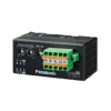
| 品名 | SC-HG1-485 |
| 型號 | SC-HG1-485 |
| 產品 | RS-485 Communication Unit for Digital Displacement Sensors |
| 產品名稱 | 數位位移感測器通信模組SC-HG1 |
|
| 品名 | SC-HG1-C |
| 型號 | SC-HG1-C |
| 產品 | CC-Link Communication Unit for Digital Displacement Sensors |
| 產品名稱 | 數位位移感測器通信模組SC-HG1 |
|
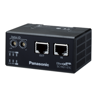
| 品名 | SC-HG1-ETC |
| 型號 | SC-HG1-ETC |
| 產品 | EtherCAT communication unit |
| 產品名稱 | 數位位移感測器通信模組SC-HG1 |

- (02)2757-1808 授理時間 9:00-17:30(除敝司休假日)
