
 Business
> Industrial Devices
> Automation Controls Top
> FA Sensors & Components
> Timers / Counters / FA Componets
> Counters
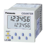
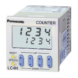
> LC4H-L Electronic Counters(DIN 48)
Business
> Industrial Devices
> Automation Controls Top
> FA Sensors & Components
> Timers / Counters / FA Componets
> Counters
> LC4H-L Electronic Counters(DIN 48)
LC4H-L Electronic Counters(DIN 48)
|
Discontinuation plan
|
|
Economical electronic counters
|


 |
 |
 |
UL/C-UL
, CE
, UKCA
Approved
Features
1.Display is a bright reflective-type LCD
2.Inherits all of the characteristics of LC4H electronic counter (Easy operation, shortened body and IP66 environmental protection)
3.Replaceable panel cover
Panel design can be changed from standard (ash gray) to black (sold separately)
4.Reasonable price
Setting The Operation Mode and Set Value
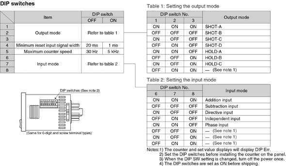
1.Setting the operation mode (input mode and output mode)
Set the input and output modes with the DIP switches on the side of the counter.
|
2.Setting the set value
Set the set value with the UP and DOWN keys on the front of the counter.
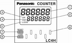
Front display section
4-digit display type
|
|
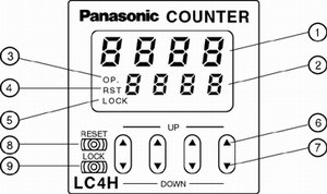
6-digit display type
|
|
3.Changing the set value
1.It is possible to change the set value with the up and down keys (4- digit type only) even during counting. However, be aware of the following points.
- 1.If the set value is changed to less than the count value with counting set to the addition direction, counting will continue until it reaches full scale (9999 with the 4-digit type and 999999 with the 6-digit type), returns to zero, and then reaches the new set value. If the set value is changed to a value above the count value, counting will continue until the count value reaches the new set value.
- 2.Suppose that the counter is preset to count down. Whether a preset countdown value is smaller or larger than the count value, the counter counts down to "0(Zero)".
2.If the set value is changed to "0," the unit will not complete count-up. It starts counting up when the counting value comes to "0 (Zero)" again.
- 1.Up-count (addition) input when counting is set to the addition direction, counting will continue until full scale is reached (9999 with the 4-digit type and 999999 with the 6-digit type), return to zero, and then complete count-up.
- 2.Down-count (subtraction) input when counting is set to the subtraction direction, counting will continue until full scale is reached (-999 with the 4-digit type and -99999 with the 6-digit type), and then the display will change to [- - - -] with the 4-digit type and [- - - - - -] with the 6-digit type. The counting value does not become "0" and so the counter does not count up.
- 3.For directive, independent, and phase input, when the counting value increases or decreases from the value "0" and then returns back to the value "0," count-up is completed.
Operation Modes
1.Input mode
For the input mode, you can choose one of the following five modes
- Addition [UP]
- Subtraction [DOWN]
- Directive [DIR]
- Independent [IND]
- Phase [PHASE]
| Input mode | Operation | *Minimum input signal width 30 Hz: 16.7 ms; 5 kHz: 0.1 ms |
|---|---|---|
| Addition [UP] |
IN1 or IN2 works as an input block (gate) for the other input. | Example where IN1 is the count counting and IN2 is the input block (gate).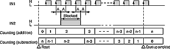 Example where IN2 is the counting input and IN1 is the input block (gate). 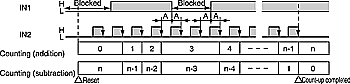 *"A" must be more than the minimum input signal width. |
| Subtraction [DOWN] |
||
| Directive [DIR] |
IIN1 is the counting input and IN2 is the addition or subtraction directive input. IN2 adds at L level and subtracts at H level. | 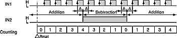 * "A" must be more than the minimum input signal width. |
| Independent [IND] |
IN1 is addition input and IN2 is subtraction input. | 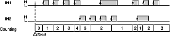 IN1 and IN2 are completely independent, so there is no restriction on signal timing. |
| Phase [PHASE] |
Addition when the IN1 phase advances beyond IN2, and subtraction when the IN2 phase advances beyond IN1. | 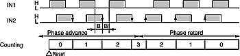 * "B" must be more than the minimum input signal width. |
2.Output mode
For the output mode, you can choose one of the following seven modes
- Maintain output/hold count [HOLD-A]
- Maintain output/over count I [HOLD-B]
- Maintain output/over count II [HOLD-C]
- One shot/over count [SHOT-A]
- One shot/recount I [SHOT-B]
- One shot/recount II [SHOT-C]
- One shot/hold count [SHOT-D]
| Output mode | Operation | (Example when input mode is either addition or subtraction) |
|---|---|---|
| Maintain output Hold count [HOLD-A] |
Output control is maintained after count-up completion and until resetting. During that time, the count display does not change from that at count-up completion. | 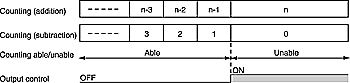 *n:Set value |
| Maintain output Over count I [HOLD-B] |
Output control is maintained after count-up completion and until resetting. However, counting is possible despite completion of count-up. | 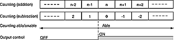 *n:Set value |
| Maintain output Over count II [HOLD-C] |
Output control is maintained after count-up completion and until the next signal enters. However, counting is possible despite completion of countup. | 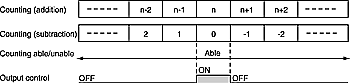 *n:Set value |
| One shot Over count [SHOT-A] |
Output control is maintained after count-up completion for a fixed time (approx. 1 sec). Counting is possible despite completion of count-up. | 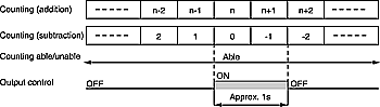 *n:Set value |
| One shot Recount I [SHOT-B] |
Output control is maintained after count-up completion for a fixed time (approx. 1 sec). Counting is possible despite completion of count-up. However, reset occurs simultaneous with completion of count-up. While output is being maintained, restarting of the count is not possible | 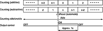 *n:Set value |
| One shot Recount II [SHOT-C] |
Output control is maintained after count-up completion for a fixed time (approx. 1 sec). Counting is possible despite completion of count-up. However, reset occurs simultaneous with output OFF. | 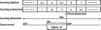 *n:Set value |
| One shot Hold count [SHOT-D] |
Output control is maintained after count-up completion for a fixed time (approx. 1 sec). During that time, the count display does not change from that at count-up completion. Reset occurs simultaneous with output OFF. | 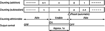 *n:Set value |
BY EMAIL


Requests to customers (Automation Control Components & Industrial Device) [Excluding specific product]
Requests to customers (Automation Control Components & Industrial Device) [For specific product]
Requests to customers (FA Sensors & Components [Excluding motors])
Requests to customers (Dedicated to industrial motors)
- COMPONENTS & DEVICES
- FA SENSORS & COMPONENTS
- Fiber Sensors
- Photoelectric Sensors / Laser Sensors
- Micro Photoelectric Sensors
- Light Curtains / Safety Components
- Area Sensors
- Inductive Proximity Sensors
- Particular Use Sensors
- Sensor Options
- Wire-Saving Systems
- Programmable Controllers / Interface Terminal
- Human Machine Interface
- Pressure Sensors / Flow Sensors
- Measurement Sensors
- Static Control Devices
- Laser Markers / 2D Code Readers
- Machine Vision System
- Energy Management Solutions
- Timers / Counters / FA Components
- MOTORS
![]()