[System Maintenance Notice]
Due to ongoing system maintenance, the site search and specification search functions are temporarily unavailable. We apologize for any inconvenience this may cause and appreciate your understanding.
【Notification of Manufacturer Change for Panasonic Industrial Devices SUNX Products and Panasonic Industrial Devices SUNX Tatsuno Products】
From April 1, 2024, the terms "Panasonic Industrial Devices SUNX Co., Ltd." and "Panasonic Industrial Devices SUNX Tatsuno Co., Ltd."
in this page and in the manuals and other documents to be downloaded will all be replaced with "Panasonic Industry Co., Ltd." and applied accordingly.
 Business
> Industrial Devices
> Automation Controls Top
> FA Sensors & Components
> Timers / Counters / FA Componets
> Timers
> Timer-related terminology
Timer-related terminology
What is The Timer?
The timer is a relay having such an output (with or without contact) which electrically closes (turns ON) or opens (turns OFF) the circuit after a preset time elapses when electrical or mechanical input is given.
On-delay Operation (Time Delay Operation)
The on-delay operation is an operation to give output when preset time expires after a predetermined input is given to the power supply circuit or input circuit.
On-delay operation includes power supply on-delay operation and signal on-delay operation.
|
Off-delay Operation (Time Delay Resetting)
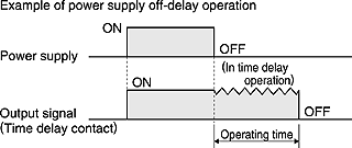
The off-delay operation is an operation to turn OFF output when preset time expires after a predetermined input is given to the power supply circuit or input circuit, and at the same time output signal is given and predetermined input is turned OFF. On-delay operation includes power supply off-delay operation and signal off-delay operation.
|
Flicker Operation
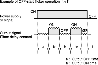
The flicker operation is an operation to repeat output ON/OFF action according to preset ON time and OFF time while a predetermined input is given to the power supply circuit or input circuit. Flicker operation includes OFF-start flicker operation and ON-start flicker operation.
|
Star ( )/Delta (△) Operation
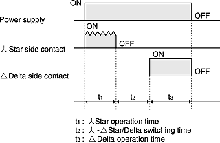
This operation controls the time in the star connection used for star-delta starting which is conducted for starting a cage induction motor and the time for switching the star connection over to delta connection.
|
Preset Time
The preset time is the control time set by setting time-variable timer.
Operating Time
The operating time means the time which elapses between the addition of predetermined input to the power supply circuit and input circuit and the completion of operation for preset time.
Hold Time
It means the time which elapses between the completion of operation for preset time and the start of resetting.
Pause Time
It means the time elapses between the start of operation for preset time and the addition of input required again for the power supply circuit or input circuit. Timer does not perform normal function unless this pause time is set longer than the timer reset time.
Resetting
It means that the operation returns to the state before starting while the timer is in operation for preset time or after it completes the operation for preset time. Resetting during the operation for preset time is referred to as halfway resetting.
Reset Time
It means the time elapses between shut-off of input to the power supply circuit or input of reset signal and the completion of resetting.
Timer resetting function shares the reset of contact, reset of mechanical parts such as pointer etc., reset of parts in internal circuit such as capacitor etc., and the value at which all of these parts complete their resetting operation is regarded as reset time. If timer is used for a pause time shorter than specified reset time, the operation time expires earlier than preset, unexpected instantaneous operation takes place or the operation is failed, thus making it impossible to expect the normal operation. Therefore, be sure to set the timer pause time longer than the specified reset time.
|
Minimum Power Application Time
It means the minimum time during which power must be supplied in order to operate timer normally, in the case of power supply off-delay timer.
Fluctuation of Operating Time
It means the irregularity in operating time caused when timer is set at specified time and the operation is repeated under the same conditions. It is also referred to as repetitive error.
Voltage Error
It means the difference between the operating time at the rated voltage and that within the allowable voltage range.
Temperature Error
It means the difference between the operating time at the temperature of 20°±2°C and that within the allowable temperature range.
Set Error
It means the difference between the set time and the time which actually elapses. It is also referred to as setting error.
The set error of an analog timer is the rate to the maximum scale value. If the set error is ±5%, it becomes equivalent to an error of maximum ±5 hours on the assumption that 100 hours is set in the range of 100 hours. The error produced when 10 hours is set is also equivalent to an error of maximum ±5 hours. As far as the set error is concerned, digital timer is by far exact. Select a digital timer for the case when accuracy is required.
When using an analog type multi-range timer for setting of long time, the setting procedure stated as follows minimizes the error. For example, if you want to set 8 hours in the range of 10 hours, first set the pointer to such a graduation where the actual operating time should become as close to 8 seconds as possible in the range of 10 seconds. Then, reset the range to 10 hours, leaving the pointer set at the graduation as it is.
Pause Time Error
It means the difference between the operating time to a fixed pause time and the operating time to a pause time that varies.
The pause time characteristics are the main characteristics of CR timer (timer exploiting charge and discharge of capacitor C and resistance R).
If the oscillation count timer (timer which comprises an oscillation circuit composed of CR and quartz and is operated by a counting circuit inside IC or micro-computer which counts the reference signal) is used, the pause time error becomes almost negligible owing to its principles of operation. Accordingly, the description about these characteristics may be omitted for the oscillation count timer.
Equation for Each Error and Measurement Conditions
The operation time shall be measured, in principle, for retention time of 0.5 second and halt time of 1 second.
The measurement shall be repeated five times except for the initial test. The equation for each error and the measurement conditions are shown in the table below:
| Error | Equation | Measurement conditions | ||
|---|---|---|---|---|
| Set value Ts - Note 1 | Supply voltage | Ambient temperature | ||
| (1) Fluctuation in operation time | ±1/2×(Tmax.-Tmin.)/TMs×100(%) | Maximum scale-time | Rated voltage | 20±2°C/ 68±36°F Note 2 |
| (2) Voltage error | (TMx1-TM)/TMs×100(%) | Fluctuation range of allowable voltage of power supply Note 3 | ||
| (3) Temperature error | (TMx2-TM)/TMs×100(%) | Rated voltage | -10 to 50°C/ +14 to 122°F Note 4 | |
| (4) Set error | (TM-Ts)/TMs×100(%) | 1/3 or more of maximum scale-time | 20±2°C/ 68±36°F Note 2 | |
| (5) Halt time error | (TMx3-TM)/TMs×100(%) | Maximum scale-time | ||
| Note 1 | For digital timers, the set value Ts shall be optional. |
|---|---|
| Note 2 | If no question arises from evaluation results, 13-35°C is acceptable. |
| Note 3 | The measurement may be performed in other specified voltage ranges. |
| Note 4 | The measurement may be performed in other specified temperature ranges. |
| TM | : | Average of measured values for operation time |
|---|---|---|
| Ts | : | Set value |
| TMs | : | Maximum scale-value. For digital timers, any arbitrary scale-value may be used. |
| Tmax | : | Maximum of measured values for operation time |
| Tmin | : | Minimum of measured values for operation time |
| TMx1 | : | Average of operation time at such voltage as maximizes deviation from TM in allowable voltage range. |
| TMx2 | : | Average of operation time at such temperature as maximizes deviation from TM in allowable temperature range. |
| TMx3 | : | Average of operation time at such halt time (in the range from the specified recovery time to 1 hour) as maximizes deviation from TM. |
Vibration Resistance, Functional
Means such a vibration as occurs in the range where the contact closed with that vibration during the use of the timer remains closed for the specified time (3 or 1 msec.) minimum.
Vibration Resistance, Destructive
Means such a vibration as occurs in the range where no part is damage with that vibration during the transportation or use of the timer.
Shock Resistance, Functional
Means such a shock as occurs in the range where the contact closed with that shock during the use of the timer remains closed for the specified time (1 ms) minimum.
Shock Resistance, Destructive
Means such a shock as occurs in the range where no part is damaged with that shock during the transportation or use of the timer and the operation characteristics are maintained.
Mechanical Life
Means the durability that is achieved when the control output is performed in the no-load state.
Electrical Life
Means the durability that is achieved when the specified voltage and current loads are individually applied to the control output while being turned ON and OFF.
Generally, the life of the timer is represented by the number of times the control output is performed.
When a load is connected to the control output, the term of "electrical life" is used.
When no load is connected to the control output, the term of "mechanical life" is used.
The electrical life is shorter than the mechanical life, and becomes longer as the load decreases.
The life of the timer is made longer by connecting a relay or a similar part rather than directly switching a large load with the control output.
Rated Power Consumption
Means the power that is consumed when the rated operation voltage is applied to the power circuit.
(Rated power consumption = rated voltage × current consumption)
Rated Control Capacity
Means the reference value that is used to determine the performance of the switching part of the load.
This value is represented by the combination of voltage and current.
Contact Resistance
Means the combined resistance that consists of the contact resistance between contacts, and the conductor resistance of pins and contact springs.
Insulation Resistance
Means the resistance between a contact or a conductive pin like the pin to which the operation voltage is applied, and a dead pin or a non-conductive metallic part like the time case, the base, or a retaining screw; or the resistance between contacts.
Withstand Voltage
Means the limit value that does not cause breakdown when high voltage is applied for one minute to the same location as measured for insulation resistance.
The detectable leak current is normally 10 mA.
In special cases, however, it may be 1 or 3 mA.
Withstand Surge Voltage
Means the limit value that shows the durability against momentary abnormal voltage resulting from lightning or switching a conductive load.
The surge waveform is represented by the standard impulsive voltage waveform at ±(1.2×50)μs or ±(1×40)μs.
BY EMAIL
Requests to customers (Automation Control Components & Industrial Device) [Excluding specific product]
Requests to customers (Automation Control Components & Industrial Device) [For specific product]
Requests to customers (FA Sensors & Components [Excluding motors])
Requests to customers (Dedicated to industrial motors)
- COMPONENTS & DEVICES
- FA SENSORS & COMPONENTS
- Fiber Sensors
- Photoelectric Sensors / Laser Sensors
- Micro Photoelectric Sensors
- Light Curtains / Safety Components
- Area Sensors
- Inductive Proximity Sensors
- Particular Use Sensors
- Sensor Options
- Wire-Saving Systems
- Programmable Controllers / Interface Terminal
- Human Machine Interface
- Pressure Sensors / Flow Sensors
- Measurement Sensors
- Static Control Devices
- Laser Markers / 2D Code Readers
- Machine Vision System
- Energy Management Solutions
- Timers / Counters / FA Components
- MOTORS


