[System Maintenance Notice]
Due to ongoing system maintenance, the site search and specification search functions are temporarily unavailable. We apologize for any inconvenience this may cause and appreciate your understanding.
【Notification of Manufacturer Change for Panasonic Industrial Devices SUNX Products and Panasonic Industrial Devices SUNX Tatsuno Products】
From April 1, 2024, the terms "Panasonic Industrial Devices SUNX Co., Ltd." and "Panasonic Industrial Devices SUNX Tatsuno Co., Ltd."
in this page and in the manuals and other documents to be downloaded will all be replaced with "Panasonic Industry Co., Ltd." and applied accordingly.
 Business
> Industrial Devices
> Automation Controls Top
> FA Sensors & Components
> Timers / Counters / FA Componets
> Timers
> LT4H-W Digital Timers(DIN 48)
LT4H-W Digital Timers(DIN 48)
|
Discontinuation plan
|
|
Easy-to-read, user-friendly
twin timers with a short body
|
 |
 |
 |
UL/C-UL
, CE
, UKCA
Approved
Features
1.Wide time range
Operation time range: 0.01 sec. to 9999 hours.
2.Bright and easy-to-read display
Bright 2-color back light LCD display.
3.Simple Operation
Seesaw buttons make operating the unit even easier than before.
4.Short body
70.1 mm 2.760 in (Pin type) 64.5 mm 2.539 in (Screw terminal type)
5.IP66 compliant for resistance against negative environmental influences (only when panel surface uses rubber gasket)
6.Screw terminal (M3.5) and pin types are both standard options
7.Replaceable panel cover
Panel design can be changed from standard (ash gray) to black (sold separately)
Setting the Operation Mode and Time Range
Setting procedure 1) Setting the time range (Timer T1/Timer T2)
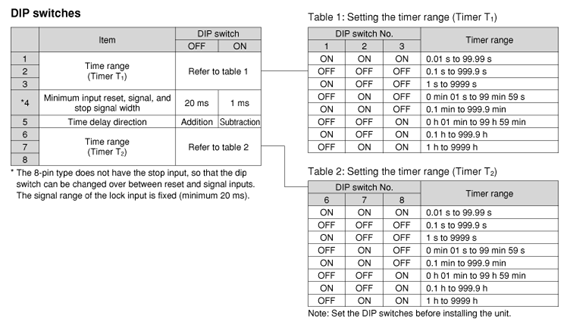
Set the time range with the DIP switches on the side of the LT4H-W timer.
Set the time range with the DIP switches on the side of the LT4H-W timer.
|
Setting procedure 2) Setting the operation mode
Set the operation mode with the keys on the front of the LT4H-W timer.|
|
 |
1)Setting or changing the operation mode
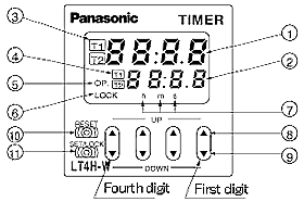
1.When the UP or DOWN key at the first digit is pressed with the SET/LOCK switch pressed, the mode is changed over to the setting mode.
|
2.Now release the SET/LOCK switch.
3.The operation mode in the setting mode is changed over sequentially in the left or right direction by pressing the UP or DOWN key at the first digit, respectively.
|
4.The operational mode displayed at present is set by pressing the RESET switch, and the display returns to the normal condition.
2)Setting (changing) the time
1.Pressing the SET/LOCK key switches the set value display between T1 and T2. Display the timer (T1 or T2) which is to be set (or changed).2.After displaying the timer (T1 or T2) which is to be set, press the UP or DOWN key to change the time.
Checking the operation mode
When the UP or DOWN key at the second digit is pressed with the SET/LOCK switch pressed, the operational mode can be checked.The display returns to the normal condition after indicating the operational mode for about two seconds. (While the display indicates the operational mode for about two seconds, the other indicators continue to operate normally.)
Setting the lock
When the UP or DOWN key at the fourth digit is pressed with the SET/LOCK switch pressed, all keys on the unit are locked.The timer does not accept any of UP, DOWN and RESET keys.
To release the lock setting, press the UP or DOWN key at the fourth digit again with the set/lock switch pressed.
*Operational mode, adding and subtracting and minimum input signal range cannot be set at T1 and T2, respectively.
Changing over the T1 and T2 setting display
The T1/T2 setting display is changed over by pressing the SET/LOCK switch. (This operation gives no effect on the other operations. The set time and elapsed time (residual time) at T1 are linked with those at T2.)Changing the set time
- 1.It is possible to change the set time with the UP and DOWN keys even during time delay with the timer. However, be aware of the following points.
- 1.If the set time is changed to less than the elapsed time with the time delay set to the addition direction, time delay will continue until the elapsed time reaches full scale, returns to zero, and then reaches the new set time. If the set time is changed to a time above the elapsed time, the time delay will continue until the elapsed time reaches the new set time.
- 2.If the time delay is set to the subtraction direction, time delay will continue until “0” regardless of the new set time.
- 2. When the set times at T1 and T2 are set to 0, the output becomes ON only while the start input is carried out.However, while the reset input is carried out, the output becomes OFF.
Operation Mode
[PULSE]:Pulse input
| A Delayed one shot |
[PULSE] [A] OFF-start/1 operation t1 < T1, t2 < T2 ・Elapsed value cleared when power is turned on. ・Time limit start initiated when start input goes on; start input ignored if time limit interval is in progress. ・Elapsed value cleared when one operation has been completed. |
|---|---|
| B OFF-start flicker |
[PULSE] [B] OFF-start/repeating operation t1 < T1, t2 < T2 ・Elapsed value cleared when power is turned on. ・Time limit start initiated when start input goes on; start input ignored if time limit interval. |
| C ON-start flicker |
[PULSE] [C] ON-start/repeating operation t1 < T1, t2 < T2 ・Elapsed value cleared when power is turned on. ・Time limit start initiated when start input goes on; start input ignored if time limit interval is in progress. |
| Remarks and notes |
・The pulse input mode starts the operation by starting the start input. ・When using the unit by starting it with the power on, shortcircuit the start terminal (8-pin: Q to R, 11-pin: E to Y and screw terminal: to ). |
|
・Each signal input such as start, reset, stop and lock inputs is applied by short-circuiting its input terminal and common terminal (8-pin type: terminal Q, 11-pin type: terminal E and screw terminal: terminal ) respectively. ・The 8-pin type does not have a stop input or lock input. |
[INTEGRATION]:Integrating input
| A Delayed one shot |
[INTEGRATION] [A] OFF-start/1 operation t1 < T1, t2 < T2 ・Elapsed value not cleared when power is turned on (power failure backup function). ・When power is turned back on, same status is maintained for output as that previous to power going off. ・Elapsed value cleared when one operation has been completed. |
|---|---|
| B OFF-start flicker |
[INTEGRATION] [B] OFF-start/repeating operation t1 < T1, t2 < T2 ・Elapsed value not cleared when power is turned on (power failure backup function). ・When power is turned back on, same status is maintained for output as that previous |
| C ON-start flicker |
[INTEGRATION] [C] ON-start/repeating operation t1 < T1, t2 < T2 ・Elapsed value not cleared when power is turned on (power failure backup function). ・When power is turned back on, same status is maintained for output as that previous to power going off. |
| Remarks and notes |
・The integrating input mode is operated by the integrated time of the start input. In other word, the timer operates only when the start input is performed. ・When the elapsed value is cleared by the reset input, the output is reset. ・When using the unit by starting it with the power on, shortcircuit the start terminal (8-pin: Q to R, 11-pin: E to Y and screw terminal: to ). |
|
・Each signal input such as start, reset, stop and lock inputs is applied by short-circuiting its input terminal and common terminal (8-pin type: terminal Q, 11-pin type: terminal E and screw terminal: terminal ) respectively. ・The 8-pin type does not have a stop input or lock input. |
BY EMAIL
Requests to customers (Automation Control Components & Industrial Device) [Excluding specific product]
Requests to customers (Automation Control Components & Industrial Device) [For specific product]
Requests to customers (FA Sensors & Components [Excluding motors])
Requests to customers (Dedicated to industrial motors)
- COMPONENTS & DEVICES
- FA SENSORS & COMPONENTS
- Fiber Sensors
- Photoelectric Sensors / Laser Sensors
- Micro Photoelectric Sensors
- Light Curtains / Safety Components
- Area Sensors
- Inductive Proximity Sensors
- Particular Use Sensors
- Sensor Options
- Wire-Saving Systems
- Programmable Controllers / Interface Terminal
- Human Machine Interface
- Pressure Sensors / Flow Sensors
- Measurement Sensors
- Static Control Devices
- Laser Markers / 2D Code Readers
- Machine Vision System
- Energy Management Solutions
- Timers / Counters / FA Components
- MOTORS


