
 Business
> Industrial Devices
> Automation Controls Top
> FA Sensors & Components
> Measurement Sensors
> Measurement Sensors
> Metal-sheet Double-feed Detector GD(Discontinued Products)
> I/O Circuit and Wiring diagrams
Business
> Industrial Devices
> Automation Controls Top
> FA Sensors & Components
> Measurement Sensors
> Measurement Sensors
> Metal-sheet Double-feed Detector GD(Discontinued Products)
> I/O Circuit and Wiring diagrams
Metal-sheet Double-feed Detector GD (Discontinued Products)
|
We are sorry, the products have been discontinued. Please refer to the details of the discontinued products and the recommended substitutes list below.
|
I/O Circuit and Wiring diagrams
Wiring diagram
|

| Non-voltage contact or NPN open-collector transistor |
 |
| Low : 0 to 1 V High: 4.5 to 30 V, or open |
Note:
Terminal [2, 0 V of power supply, is isolated from 0 V of input / output circuitry for noise immunity. However, if you expect to share the power supply with the output loads, connect terminals [2] and [6] , terminals [2] and [10] , or terminals [2] and [20] to make 0 V common.
I/O circuit diagram
|
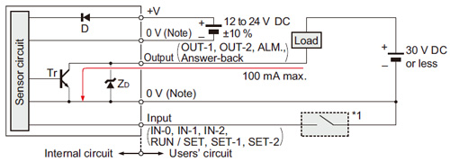
| Symbols・・・ | D : Reverse supply polarity protection diode
ZD : Surge absorption zener diode Tr : NPN output transistor |
|---|
External channel select truth table
Classification by IEC 60825-1
| Channel No. | Input | ||
|---|---|---|---|
| IN-0 | IN-1 | IN-2 | |
| 1 | L | H | H |
| 2 | H | L | H |
| 3 | L | L | H |
| 4 | H | H | L |
| 5 | L | H | L |
| 6 | H | L | L |
| 7 | L | L | L |
| 8 | H | H | H |
L: Low (0 to 1 V), H: High (4.5 to 30 V, or open)
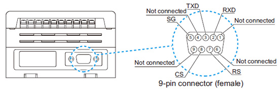
RS-232C wiring diagram (GD-C2 only)
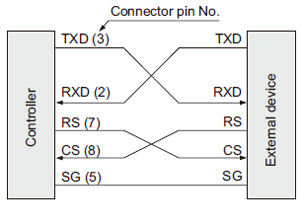 |
TXD : Transmit data, command |
|
BY EMAIL


Requests to customers (Automation Control Components & Industrial Device) [Excluding specific product]
Requests to customers (Automation Control Components & Industrial Device) [For specific product]
Requests to customers (FA Sensors & Components [Excluding motors])
Requests to customers (Dedicated to industrial motors)
- COMPONENTS & DEVICES
- FA SENSORS & COMPONENTS
- Fiber Sensors
- Photoelectric Sensors / Laser Sensors
- Micro Photoelectric Sensors
- Light Curtains / Safety Components
- Area Sensors
- Inductive Proximity Sensors
- Particular Use Sensors
- Sensor Options
- Wire-Saving Systems
- Programmable Controllers / Interface Terminal
- Human Machine Interface
- Pressure Sensors / Flow Sensors
- Measurement Sensors
- Static Control Devices
- Laser Markers / 2D Code Readers
- Machine Vision System
- Energy Management Solutions
- Timers / Counters / FA Components
- MOTORS
![]()