[System Maintenance Notice]
Due to ongoing system maintenance, the site search and specification search functions are temporarily unavailable. We apologize for any inconvenience this may cause and appreciate your understanding.
【Notification of Manufacturer Change for Panasonic Industrial Devices SUNX Products and Panasonic Industrial Devices SUNX Tatsuno Products】
From April 1, 2024, the terms "Panasonic Industrial Devices SUNX Co., Ltd." and "Panasonic Industrial Devices SUNX Tatsuno Co., Ltd."
in this page and in the manuals and other documents to be downloaded will all be replaced with "Panasonic Industry Co., Ltd." and applied accordingly.

 Business
> Industrial Devices
> Automation Controls Top
> FA Sensors & Components
> Sensors
> Area Sensors
> Ultra-slim Body Picking Sensor NA1-PK5/NA1-5
> Cautions For Use
Business
> Industrial Devices
> Automation Controls Top
> FA Sensors & Components
> Sensors
> Area Sensors
> Ultra-slim Body Picking Sensor NA1-PK5/NA1-5
> Cautions For Use
Ultra-slim Body Picking Sensor NA1-PK5/NA1-5
|
Cautions For Use
- Never use this product as a sensing device for personnel protection.
- For sensing devices to be used as safety devices for press machines or for personnel protection, use products which meet standards, such as OSHA, ANSI or IEC etc., for personnel protection applicable in each region or country.
- If this product is used as a sensing device for personnel protection, death or serious body injury could result.
- For a product which meets safety standards, use the safety light curtain.
Mounting
|
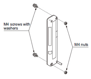 |
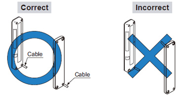
Orientation
- The emitter and the receiver must face each other correctly. If they are set upside down, the sensor does not work.
|
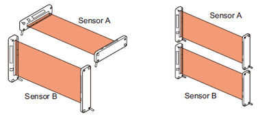
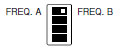
Interference prevention function
- By setting different emission frequencies, two units of the sensor can be mounted close together, as shown in the figure below.
(The switches must be set with the power supply off. The operation mode does not change if the switch setting is changed with the power supplied.)
|
| Operation mode switch | ||
|---|---|---|
| Emitter | Receiver | |
| Sensor A (FREQ. A) |
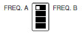 |
|
| Sensor B (FREQ. B) |
 |
|
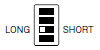
LONG / SHORT selection switch (incorporated on the emitter)
- Select the switch setting according to the setting distance between the emitter and the receiver as given below.
(The switches must be set with the power supply off. The operation mode does not change if the switch setting is changed with the power supplied.)
| Setting distance | Operation mode switch |
|---|---|
| 0.05 to 0.5 m 0.164 to 1.640 ft [NA1-PK5(-PN)] 0.05 to 1 m 0.164 to 3.281 ft [NA1-5(-PN)] |
 |
| 0.5 to 1.2 m 1.640 to 3.937 ft [NA1-PK5(-PN)] 1 to 3 m 3.281 to 9.843 ft [NA1-5(-PN)] |
 |
Selection of output operation
- The output operation mode is selected by the operation mode switch on the receiver.
(The switches must be set with the power supply off. The operation mode does not change if the switch setting is changed with the power supplied.)
| Output operation | Operation mode switch |
|---|---|
| ON when one or more beam channels are interrupted (OFF when all beam channels are received). |
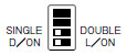 |
| OFF when one or more beam channels are interrupted (ON when all beam channels are received). |
 |
| ON when any two or more beam channels are interrupted. | 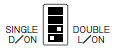 |
| OFF when any two or more beam channels are interrupted. | 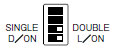 |
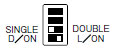
Job indicator operation selection
- Lighting / Blinking is selected by the operation mode switch on the emitter and the receiver.
(The switches must be set with the power supply off. The operation mode does not change if the switch setting is changed with the power supplied.)
| Operation mode switch | ||
|---|---|---|
| Emitter | Receiver | |
| Lighting | 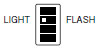 |
|
| Blinking | 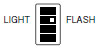 |
|
Others
- Do not use during the initial transient time (0.5 sec.) after the power supply is switched on.
BY EMAIL


Requests to customers (Automation Control Components & Industrial Device) [Excluding specific product]
Requests to customers (Automation Control Components & Industrial Device) [For specific product]
Requests to customers (FA Sensors & Components [Excluding motors])
Requests to customers (Dedicated to industrial motors)
- COMPONENTS & DEVICES
- FA SENSORS & COMPONENTS
- Fiber Sensors
- Photoelectric Sensors / Laser Sensors
- Micro Photoelectric Sensors
- Light Curtains / Safety Components
- Area Sensors
- Inductive Proximity Sensors
- Particular Use Sensors
- Sensor Options
- Wire-Saving Systems
- Programmable Controllers / Interface Terminal
- Human Machine Interface
- Pressure Sensors / Flow Sensors
- Measurement Sensors
- Static Control Devices
- Laser Markers / 2D Code Readers
- Machine Vision System
- Energy Management Solutions
- Timers / Counters / FA Components
- MOTORS
![]()