
 Business
> Industrial Devices
> Automation Controls Top
> FA Sensors & Components
> Sensors
> Sensor Options
> ON / OFF Input Sensor Controller NPS(Discontinued Products)
> Cautions For Use
Business
> Industrial Devices
> Automation Controls Top
> FA Sensors & Components
> Sensors
> Sensor Options
> ON / OFF Input Sensor Controller NPS(Discontinued Products)
> Cautions For Use
ON / OFF Input Sensor Controller NPS (Discontinued Products)
|
We are sorry, the products have been discontinued. Please refer to the details of the discontinued products and the recommended substitutes list below.
|
Cautions For Use
- Never use this product in a device for personnel protection.
- In case of using devices for personnel protection, use products which meet laws and standards, such as OSHA, ANSI or IEC etc., for personnel protection applicable in each region or country.
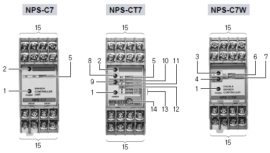
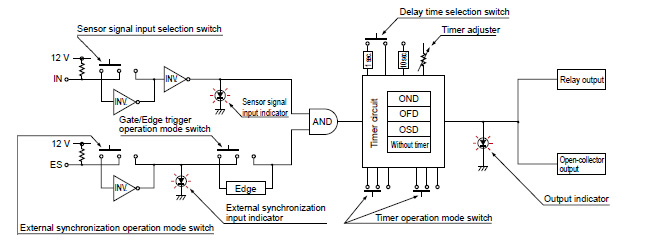
Functional description
|
| Description | Function | |
|---|---|---|
| 1 | Power indicator (Red LED) |
Lights up when the power is ON. |
| 2 | Output indicator (Red LED) |
Lights up when the output is ON. |
| 3 | Sensor 1 output indicator (Red LED) |
|
| 4 | Sensor 2 output indicator (Red LED) |
|
| 5 | Sensor signal input selection switch | Selects the output operation. NORM.: The output is ON when the sensor signal input is Low. |
| 6 | Sensor 1 output operation mode switch | Selects the output operation. NORM.: The output is ON when the sensor signal input is Low. |
| 7 | Sensor 2 output operation mode switch | |
| 8 | Sensor signal input indicator (Red LED) |
Indicates the state of the sensor signal input. The operation differs according to the mode set with 5 Sensor signal input selection switch. INV.: Lights up when the sensor signal input is High. NORM.: Lights up when the sensor signal input is Low. |
| 9 | External synchronization input indicator (Red LED) |
Indicates the state of the external synchronization input. Lights up when the external synchronization input does not disable the output. |
| 10 | External synchronization operation mode switch | Selects the operation of external synchronization. NORM.: The output is neglected when the external synchronization input is Low. |
| 11 | Gate/Edge trigger operation mode switch | Selects Gate trigger or Edge trigger.  :Effective at the instant the external synchronization input is applied. :Effective at the instant the external synchronization input is applied. :Effective over the period for which the external synchronization input is applied. :Effective over the period for which the external synchronization input is applied. |
| 12 | Timer period selection switch | Selects the timer period. 10 sec.: Variable from 0.4 sec. approx. to 10 sec. approx. |
| 13 | Timer operation mode switch | Selects the timer operation.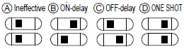 |
| 14 | Timer operation mode switch | Set the timer period. |
| 15 | Terminal block | ー |
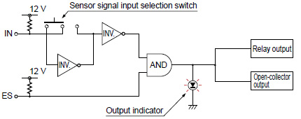
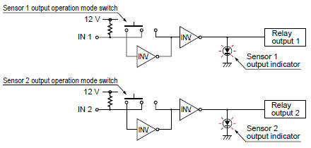
Block diagrams (The diagrams below explain NPS’s operation in a simple manner. The actual circuits may differ slightly.)
|
|
|
Timer functions (NPS-CT7 only)
- NPS-CT7has three types of convenient built-in timer functions.
- ON-delay (OND)
| <Function> | Neglects short output signals. |
|---|---|
| <Application> | As only long signals are extracted, this function is useful for detecting if a line is choked or for sensing only objects taking a long time to travel. |
- OFF-delay (OFD)
| <Function> | Extends the output signal for a fixed period of time. |
|---|---|
| <Application> | This function is useful if the output signal is so short that the connected device cannot respond. |
- ONE SHOT (OSD)
| <Function> | Outputs a fixed width signal upon sensing. |
|---|---|
| <Application> | This function is useful when the input specifications of the connected device require a signal of fixed width. Of course, it is also useful for extending a short width signal to a desired width. |
Various other applications are possible.
Selection switch and timer operation
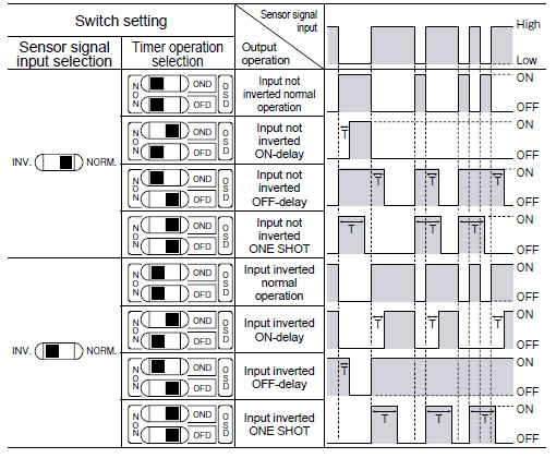
Timer period: T =Switchable, either 40 ms approx. to 1 sec. approx., or 0.4 sec. approx. to 10 sec. approx.
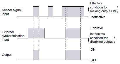
External synchronization function (NPS-C7, NPS-CT7 only)
- Gate trigger
The output is disabled when the external synchronization input is Low [mode selection switch on NORM. (Note)] or is High [mode selection switch on INV. (Note)].
|
| Note: | SinceNPS-C7 is not incorporated with the selection switch, the output is disabled only when the external synchronization input is Low. |
|---|
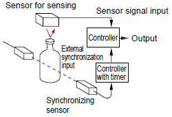
- Edge trigger (NPS-CT7 only)
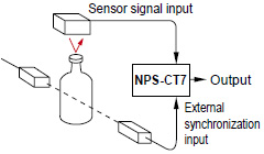
The sensor signal is judged at the instant the external synchronization input rises up or falls down. This sensor is ideal for cap presence detection that would have required two controllers in the past.
Example: Detecting presence of cap on bottle
|
|
|
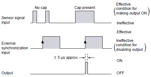
| Note: | As the output time‘t’is only 5 μs approx., extend it by using the OFFdelay timer or the ONE SHOT timer. |
|---|
Mounting
- To mount NPS with screws, use M4 screws.
The tightening torque should be 0.78 N•m or less.
Wiring
- Make sure that the power supply is off while wiring.
- Verify that the supply voltage variation is within the rating.
- Short-circuit protection plate
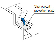 |
The short-circuit protection plate is attached to terminal No. 1 to prevent AC short-circuit. Flip the plate up, connect the wire to terminal No. 1, and then flip it down. (The short-circuit protection plate is attached at the time of shipment from our factory.) |
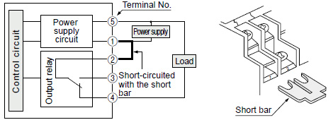
- Short bar
The short bar saves wiring when a common power supply is used for the AC supply terminal and the load supply of the relay contact output.
(The short bar is attached between the terminal Nos. 1 and 2 at the time of shipment from our factory. To use a separate power supply for the output relay, make sure to remove it.)
Typical wiring diagram
|
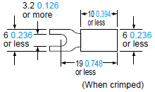
- Dimensions of suitable crimp terminals
(Unit: mm in)
| Y-shaped type | Round type |
|---|---|
 |
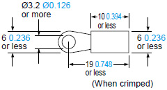 |
| Note: | Use crimp terminals having insulation sleeves. Recommended crimp terminal: Nominal size 1.25-3.0 |
|---|
- NPS-C7andNPS-CT7do not incorporate a short-circuit protection at the NPN open-collector transistor output.
Do not connect them directly to a power supply or a capacitive load. - The response time of the NPN open-collector transistor output of NPS-CT7 or NPS-CT7 is 5 μs. If a relay or a micro-switch (mechanical contact) is connected, take care since its bounce may result in output chattering.
- Do not run the wires together with high-voltage lines or power lines or put them in the same raceway. This can cause malfunction due to induction.
Others
- Do not use during the initial transient time (0.5 sec.) after the power supply is switched on.
- Avoid dust, dirt, and steam.
- Take care that the controller does not come in direct contact with water, oil, grease, or organic solvents, such as, thinner, etc.
BY EMAIL


Requests to customers (Automation Control Components & Industrial Device) [Excluding specific product]
Requests to customers (Automation Control Components & Industrial Device) [For specific product]
Requests to customers (FA Sensors & Components [Excluding motors])
Requests to customers (Dedicated to industrial motors)
- COMPONENTS & DEVICES
- FA SENSORS & COMPONENTS
- Fiber Sensors
- Photoelectric Sensors / Laser Sensors
- Micro Photoelectric Sensors
- Light Curtains / Safety Components
- Area Sensors
- Inductive Proximity Sensors
- Particular Use Sensors
- Sensor Options
- Wire-Saving Systems
- Programmable Controllers / Interface Terminal
- Human Machine Interface
- Pressure Sensors / Flow Sensors
- Measurement Sensors
- Static Control Devices
- Laser Markers / 2D Code Readers
- Machine Vision System
- Energy Management Solutions
- Timers / Counters / FA Components
- MOTORS
![]()