[System Maintenance Notice]
Due to ongoing system maintenance, the site search and specification search functions are temporarily unavailable. We apologize for any inconvenience this may cause and appreciate your understanding.
【Notification of Manufacturer Change for Panasonic Industrial Devices SUNX Products and Panasonic Industrial Devices SUNX Tatsuno Products】
From April 1, 2024, the terms "Panasonic Industrial Devices SUNX Co., Ltd." and "Panasonic Industrial Devices SUNX Tatsuno Co., Ltd."
in this page and in the manuals and other documents to be downloaded will all be replaced with "Panasonic Industry Co., Ltd." and applied accordingly.
Compact Photoelectric Sensor CX-400 Ver.2
Partly Order Discontinued
|
|
I/O Circuit and Wiring diagrams
NPN output type
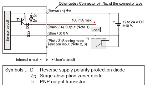
I/O circuit diagram
Notes:
| 1) |
The emitter of the thru-beam type sensor does not incorporate the output. |
| 2) |
Sensing mode selection input is incorporated only for the CX-44□ adjustable range reflective type. When using the CX-44□, be sure to wire the sensing mode selection input (pink / 2) as mentioned*1. Unstable operation may occur. |
| 3) |
When the mating cable is connected to the plug-in connector type of CX-44□, its color is white. |
*1:
Sensing mode selection input
BGS function: Connect to 0 V
FGS function: Connect to +V
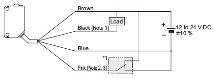
Wiring diagram
Notes:
| 1) |
The emitter of the thru-beam type sensor does not incorporate the black wire. |
| 2) |
The pink wire is incorporated only for the CX-44□ adjustable range reflective type. When using the CX-44□, be sure to wire the pink wire as mentioned*1. Unstable operation may occur. |
| 3) |
When the mating cable is connected to the plug-in connector type of CX-44□, its color is white. |
*1:
Sensing mode selection input
BGS function: Connect to 0 V
FGS function: Connect to +V
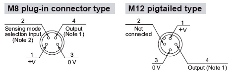
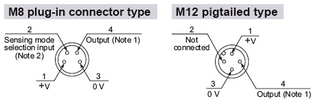
Connector pin position
Notes:
| 1) |
The emitter of the thru-beam type sensor does not incorporate the output. |
| 2) |
Sensing mode selection input is incorporated only for the CX-44□ adjustable range reflective type. When using the CX-44□, be sure to wire the sensing mode selection input (pink / 2). Unstable operation may occur. |
PNP output type
I/O circuit diagram
Notes:
| 1) |
The emitter of the thru-beam type sensor does not incorporate the output. |
| 2) |
Sensing mode selection input is incorporated only for the CX-44□-P adjustable range reflective type. When using the CX-44□-P, be sure to wire the sensing mode selection input (pink / 2) as mentioned*1. Unstable operation may occur. |
| 3) |
When the mating cable is connected to the plug-in connector type of CX-44□-P, its color is white. |
*1:
Sensing mode selection input
BGS function: Connect to 0 V
FGS function: Connect to +V
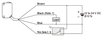
Wiring diagram
Notes:
| 1) |
The emitter of the thru-beam type sensor does not incorporate the black wire. |
| 2) |
The pink wire is incorporated only for the CX-44□-P adjustable range reflective type. When using the CX-44□-P, be sure to wire the pink wire as mentioned*1. Unstable operation may occur. |
| 3) |
When the mating cable is connected to the plug-in connector type of CX-44□-P, its color is white. |
*1:
Sensing mode selection input
BGS function: Connect to 0 V
FGS function: Connect to +V
Connector pin position
Notes:
| 1) |
The emitter of the thru-beam type sensor does not incorporate the output. |
| 2) |
Sensing mode selection input is incorporated only for the CX-44□-P adjustable range reflective type. When using the CX-44□-P, be sure to wire the sensing mode selection input (pink / 2). Unstable operation may occur. |
Return to top
Return to top

 Business
> Industrial Devices
> Automation Controls Top
> FA Sensors & Components
> Sensors
> Photoelectric Sensors / Laser Sensors
> Compact Photoelectric Sensor CX-400 Ver.2
> I/O Circuit and Wiring diagrams
Business
> Industrial Devices
> Automation Controls Top
> FA Sensors & Components
> Sensors
> Photoelectric Sensors / Laser Sensors
> Compact Photoelectric Sensor CX-400 Ver.2
> I/O Circuit and Wiring diagrams