Amplifier Built-in Ultra-compact Laser Sensor EX-L200
I/O Circuit and Wiring diagrams
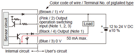
NPN output type
I/O circuit diagrams
Notes:
| 1) |
The emitter of a thru-beam type does not incorporate output (black / 4) and output operation switching input (pink / 2). |
| 2) |
Be able to select either Light-ON or Dark-ON by wiring the output operation switching input (pink / 2) as shown in the following table.
| Type |
Light-ON |
Dark-ON |
| Thru-beam, Retroreflective |
Connect to 0 V |
Connect to + V or, Open |
| Spot reflective / Convergent reflective |
Connect to + V or, Open |
Connect to 0 V |
*Insulate the output operation switching input wire (pink / 2) when leaving it open. |
| 3) |
When connecting the mating cable to the pigtailed type, color code of wire is “white”. |
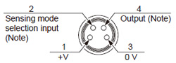
Connector pin position (pigtailed type)
| Note: |
The emitter of a thru-beam type does not incorporate output and output operation switching input. |
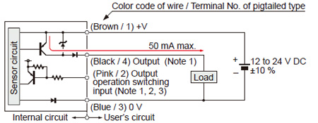
PNP output type
I/O circuit diagrams
Notes:
| 1) |
The emitter of a thru-beam type does not incorporate output (black / 4) and output operation switching input (pink / 2). |
| 2) |
Be able to select either Light-ON or Dark-ON by wiring the output operation switching input (pink / 2) as shown in the following table.
| Type |
Light-ON |
Dark-ON |
| Thru-beam, Retroreflective |
Connect to 0 V |
Connect to + V or, Open |
| Spot reflective / Convergent reflective |
Connect to + V or, Open |
Connect to 0 V |
* Insulate the output operation switching input wire (pink / 2) when leaving it open.
|
| 3) |
When connecting the mating cable to the pigtailed type, color code of wire is “white”. |
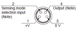
Connector pin position (pigtailed type)
| Note: |
The emitter of a thru-beam type does not incorporate output and output operation switching input. |
Return to top
Return to top

 Business
> Industrial Devices
> Automation Controls Top
> FA Sensors & Components
> Sensors
> Photoelectric Sensors / Laser Sensors
> Amplifier Built-in Ultra-compact Laser Sensor EX-L200
> I/O Circuit and Wiring diagrams
Business
> Industrial Devices
> Automation Controls Top
> FA Sensors & Components
> Sensors
> Photoelectric Sensors / Laser Sensors
> Amplifier Built-in Ultra-compact Laser Sensor EX-L200
> I/O Circuit and Wiring diagrams