[System Maintenance Notice]
Due to ongoing system maintenance, the site search and specification search functions are temporarily unavailable. We apologize for any inconvenience this may cause and appreciate your understanding.
【Notification of Manufacturer Change for Panasonic Industrial Devices SUNX Products and Panasonic Industrial Devices SUNX Tatsuno Products】
From April 1, 2024, the terms "Panasonic Industrial Devices SUNX Co., Ltd." and "Panasonic Industrial Devices SUNX Tatsuno Co., Ltd."
in this page and in the manuals and other documents to be downloaded will all be replaced with "Panasonic Industry Co., Ltd." and applied accordingly.
Cylindrical Compact Inductive Proximity Sensor GX (Discontinued Products)
We are sorry, the products have been discontinued. Please refer to the details of the discontinued products and the recommended substitutes list below.
 |
September 30, 2022 |
|
|
Cautions For Use
- Never use this product as a sensing device for personnel protection.
- In case of using sensing devices for personnel protection, use products which meet laws and standards, such as OSHA, ANSI or IEC etc., for personnel protection applicable in each region or country.
Mounting
- The tightening torque should be as given below.
<Shielded of threaded type>
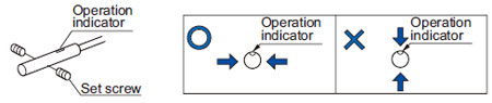
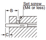
- Tighten the set screw on the flat surface of the sensor without applying excessive force. Make sure to use a set screw with a cup-point end.
 |
|
Note: To fasten GX-5M□, use a M3 or less set screw. |
| |
|
| Model No. |
Set screw tightening position A (mm in) |
Tightening torque |
| GX-5M□ |
5 to 10 0.197 to 0.394 |
0.29 N·m |
| GX-8M□ |
8 to 22 0.315 to 0.866 |
0.29 N·m |
|
<Non-threaded type and non-shielded of threaded type>
 |
|
| Model No. |
B (mm in) |
C (mm in) |
Tightening torque |
| GX-3S□ |
5 to 10
0.197 to 0.394 |
3
0.118 |
0.29 N·m |
| |
When using
the C bracket |
0.58 N·m |
| GX-4S□ |
5 to 10
0.197 to 0.394 |
3
0.118 |
0.58 N·m |
| GX-5S□ |
8 to 20
0.315 to 0.787 |
5
0.197 |
0.29 N·m |
| GX-8ML□ |
13 to 22
0.517 to 0.866 |
10
0.394 |
0.29 N·m |
| Note: |
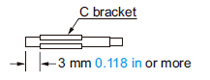
The protrusion should be kept C (mm in) or more to avoid reduction of sensing range. |
|
- To fasten GX-3S□ and GX-4S□, use a M3 or less set screw and tighten it from a direction perpendicular to the operation indicator.
- When using the C bracket, place it on the sensor at a distance of 3 mm 0.118 in or more from the sensor end.
- To fasten the non-shielded threaded type, tighten the set screw on the flat surface of the sensor.
- Note that the maximum tightening torque differs according to the location of the nuts.
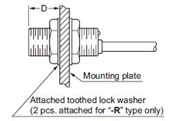
<Shielded of threaded type> |
|---|
 |
|
|
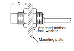
<Non-shielded of threaded type> |
|---|
 |
|
|
| Model No. |
D (mm in) |
Tightening torque |
| GX-5M□ |
2 to 3 0.079 to 0.118 |
0.49 N·m |
| 3 0.118 or more |
1.47 N·m |
| GX-8M□ |
3 to 11 0.118 to 0.433 |
1.47 N·m |
| 11 0.433 or more |
3.43 N·m |
| GX-8ML□ |
9 to 11 0.345 to 0.433 |
0.98 N·m |
| 11 0.433 or more |
3.43 N·m |
| Note: |
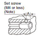
Mount such that the nuts do not protrude from the threaded portion. |
- The root truncation of the threads with GX-8M□ and GX-8ML□ is shallow owing to strengthening of the sensors against tightening.
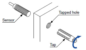
When tapped hole on equipment to fix the sensors, the prepared hole must be ø7.2 mm ø0.283 in or more.
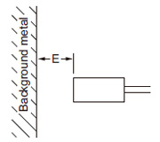
Distance from surrounding metal
- As metal around the sensor may affect the sensing performance, pay attention to the following points.
| Influence of surrounding metal |
- The surrounding metal will affect the sensing performance. Keep the minimum distance specified in the table below.
 |
|
| Model No. |
E (mm in) |
| GX-3S□ |
3 0.118 |
| GX-4S□ |
3 0.118 |
| GX-5S□ |
4 0.157 |
| GX-5M□ |
3 0.118 |
| GX-8M□ |
4 0.157 |
| GX-8ML□ |
8 0.315 |
|
| Embedding of the sensor in metal |
- Sensing range may decrease if the sensor is completely embedded in metal. Especially for the non-threaded type and the non-shielded type, keep the minimum distance specified in the table below.
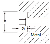 |
|
| Model No. |
F (mm in) |
G (mm in) |
| GX-3S□ |
ø12 ø0.472 |
3 0.118 |
| GX-4S□ |
ø12 ø0.472 |
3 0.118 |
| GX-5S□ |
ø15.4 ø0.606 |
5 0.197 |
| GX-8ML□ |
ø30 ø1.181 |
10 0.394 |
|
Mutual interference
- When two or more sensors are installed in parallel or face to face, keep the minimum separation distance specified below to avoid mutual interference.
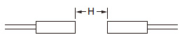
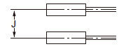
|
|
| Model No. |
H (mm in) |
J (mm in) |
| GX-3S□ |
16 0.630 |
16 0.630 |
| GX-4S□ |
16 0.630 |
16 0.630 |
| GX-5S□ |
20 0.787 |
15 0.591 |
| GX-5M□ |
10 0.394 |
10 0.394 |
| GX-8M□ |
20 0.787 |
15 0.591 |
| GX-8ML□ |
50 1.969 |
30 1.181 |
|
Sensing range
- The sensing range is specified for the standard sensing object. With a non-ferrous metal, the sensing range is obtained by multiplying with the correction coefficient specified below. Further, the sensing range also changes if the sensing object is smaller than the standard sensing object or if the sensing object is plated.
Correction coefficient
| |
GX-3S□
GX-4S□ |
GX-5M□ |
GX-5S□
GX-8M□
GX-8ML□ |
| Iron |
1 |
1 |
1 |
Stainless steel
(SUS304) |
0.65 approx. |
0.83 approx. |
0.7 approx. |
| Brass |
0.36 approx. |
0.61 approx. |
0.4 approx. |
| Aluminum |
0.30 approx. |
0.58 approx. |
0.35 approx. |
Others
- Do not use during the initial transient time (10 ms) after the power supply is switched on.
- Make sure that stress by forcible bend or pulling is not applied directly to the sensor cable joint.
- GX-3S□, GX-4S□ and GX-5M□ do not incorporate a short-circuit protection circuit at the output. Do not connect them directly to a power supply or a capacitive load.
Return to top
Return to top

 Business
> Industrial Devices
> Automation Controls Top
> FA Sensors & Components
> Sensors
> Inductive Proximity Sensors
> Cylindrical Compact Inductive Proximity Sensor GX(Discontinued Products)
> Cautions For Use
Business
> Industrial Devices
> Automation Controls Top
> FA Sensors & Components
> Sensors
> Inductive Proximity Sensors
> Cylindrical Compact Inductive Proximity Sensor GX(Discontinued Products)
> Cautions For Use