[System Maintenance Notice]
Due to ongoing system maintenance, the site search and specification search functions are temporarily unavailable. We apologize for any inconvenience this may cause and appreciate your understanding.
【Notification of Manufacturer Change for Panasonic Industrial Devices SUNX Products and Panasonic Industrial Devices SUNX Tatsuno Products】
From April 1, 2024, the terms "Panasonic Industrial Devices SUNX Co., Ltd." and "Panasonic Industrial Devices SUNX Tatsuno Co., Ltd."
in this page and in the manuals and other documents to be downloaded will all be replaced with "Panasonic Industry Co., Ltd." and applied accordingly.
Exclusive Control Unit for Safety Light Curtain SF-C10
Partly Order Discontinued
 |
March 31, 2023 |
|
|
I/O Circuit and Wiring diagrams
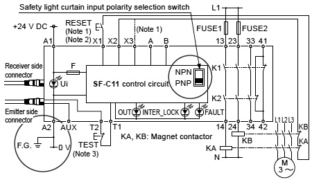
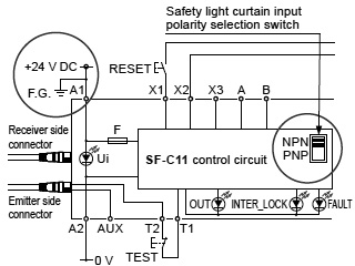
Wiring diagram of SF-C11 and SF4B / SF4B-G series or SF2B series (Control Category 4 or 2)
| For PNP output (minus ground) |
- Set the safety light curtain input polarity selection switch to the PNP side and ground the 0 V line.
| Notes: 1) |
The above diagram is when using manual reset. If automatic reset is used, disconnect the lead from X2 and connect it to X3. In this case, a reset (RESET) button is not needed. |
| 2) |
Use a momentary-type switch as the reset (RESET) button. |
| 3) |
Emission halt occurs when the test (TEST) button is open, and emission occurs when the test (TEST) button is short-circuited. If not using the test (TEST) button, short-circuit T1 and T2. However, in case of SF2B series, use a test rod or similar to interrupt the light in order to carry out self-diagnosis separately. |
| For NPN output (plus ground) |
- In the above diagram, set the safety light curtain input polarity selection switch to the NPN side and ground the + side.
|
|
| When connecting the SF-C11 to the safety light curtains, make
sure to use the 8-core connection cable with a connector. Refer
to the SF4B / SF4B-G series and SF2B series pages for details.
SFB-CB□, SF2B-CB□, SFB-CCJ10□ |
| Terminal arrangement diagram |
|
|
| Terminal |
Function |
| A1 |
+24 V DC |
| A2 |
0 V |
| 13-14, 23-24, 33-34 |
Safety output (NO contact × 3) |
| 41-42 |
Auxiliary output (NC contact × 1) |
| X1 |
Reset output terminal |
| X2 |
Reset input terminal (Manual) |
| X3 |
Reset input terminal (Automatic) |
| A |
Not used |
| B |
| T1 |
Test output terminal |
| T2 |
Test input terminal |
| AUX |
Semiconductor auxiliary output |
|
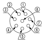
| Pin layout for safety light curtain connectors |
|
|
| Connector pin No. |
Emitter side connector |
Receiver side connector |
| ① |
Interlock(Note) |
OSSD 2 |
| ② |
+24 V DC |
+24 V DC |
| ③ |
Emission halt |
OSSD 1 |
| ④ |
Auxiliary output |
EDM (External relay monitor) |
| ⑤ |
Synchronization wire + |
Synchronization wire + |
| ⑥ |
Synchronization wire – |
Synchronization wire – |
| ⑦ |
0 V |
0 V |
| ⑧ |
Shielded wire |
Shielded wire |
Note: It is not used with the SF2B series.
|
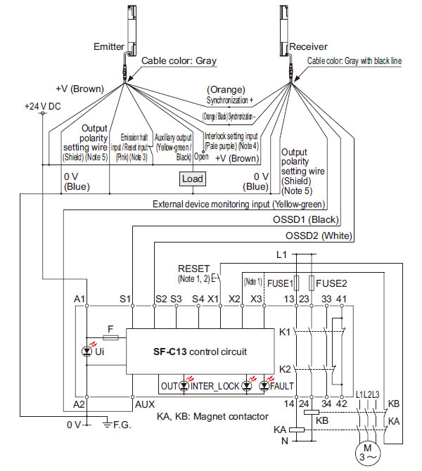
Wiring diagram of SF-C13 and SF4B / SF4B-G series or SF2B series (Control Category 4 or 2)
| For PNP output (minus ground) |
- Connect the safety light curtain control outputs OSSD1 and OSSD2 to S1 and S2 respectively.
| Notes: 1) |
The above diagram is when using manual reset. If automatic reset is used, disconnect the lead from X2 and connect it to X3. In this case, a reset (RESET) button is not needed. |
| 2) |
Use a momentary-type switch as the reset (RESET) button. |
| 3) |
This is a test input (pink) for the SF2B series. |
| 4) |
This is not equipped on the SF2B series. |
| 5) |
This is a shield for the SF2B series. Output polarity cannot be set. |
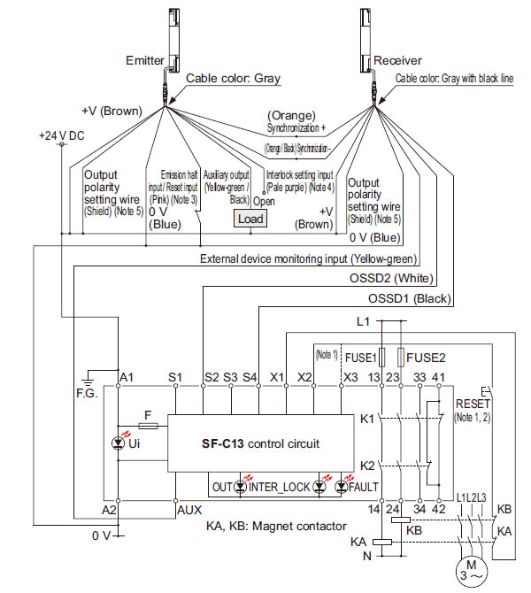
| For NPN output (plus ground) |
- Connect the safety light curtain control outputs OSSD1 and OSSD2 to S4 and S2 respectively and ground the + side.
| Notes: 1) |
The above diagram is when using manual reset. If automatic reset is used, disconnect the lead from X2 and connect it to X3. In this case, a reset (RESET) button is not needed. |
| 2) |
Use a momentary-type switch as the reset (RESET) button. |
| 3) |
This is a test input (pink) for the SF2B series. |
| 4) |
This is not equipped on the SF2B series. |
| 5) |
This is a shield for the SF2B series. Output polarity cannot be set. |
When connecting the SF-C13 to the safety light curtains, make sure to use a discrete wire connection cable. Refer to the SF4B / SF4B-G series and SF2B series pages for details.
SFB-CCB□(-MU), SF2B-CCB□, SFB-CC□(-MU) |
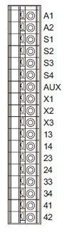
| Terminal arrangement diagram |
|
|
| Terminal |
Function |
| A1 |
+24 V DC |
| A2 |
0 V |
| S1 to S4 |
Safety light curtain control output (OSSD) input terminal |
| AUX |
Semiconductor auxiliary output |
| X1 |
Reset output terminal |
| X2 |
Reset input terminal (Manual) |
| X3 |
Reset input terminal (Automatic) |
| 13-14, 23-24, 33-34 |
Safety output (NO contact × 3) |
| 41-42 |
Auxiliary output (NC contact × 1) |
| Use a separate terminal block to carry out wiring for safety light curtains that cannot be connected to the SF-C13. |
|
Discontinued products
| For PNP output (minus ground) |
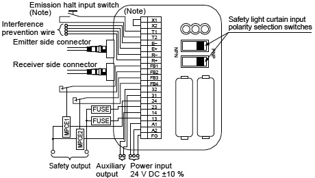
Wiring diagram of SF-C12 and SF4B series (Control category 4)
- Set the two safety light curtain input polarity selection switches
to the PNP side and connect the F.G. terminal to the 0 V line.
| Note: |
The above diagram is when using manual reset. If automatic reset is used, connect a normal close-type pushbutton switch between T1 and T2 and leave between X1 and X2 open. |
| For NPN output (plus ground) |
- In the above diagram, set the two safety light curtain input polarity selection switches to the NPN side and connect the F.G. terminal to the + side.
When connecting the SF-C12 to the safety light curtains, make sure to use the 12-core connection cable with a connector.
Refer to the SF4B / SF4B-G series pages for details.
SFB-CB05-MU (Cable length: 0.5 m 1.640 ft)
SFB-CCJ10E-MU (Extension cable for emitter, cable length: 10 m 32.808 ft)
SFB-CCJ10D-MU (Extension cable for receiver, cable length: 10 m 32.808 ft) |
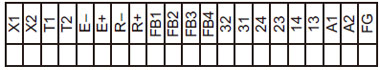
| Terminal arrangement diagram |
|
|
| Terminal |
Function |
| FG |
Frame ground (F.G.) terminal |
| A2 |
0 V |
| A1 |
+24 V DC |
| 13-14, 23-24 |
Safety output (NO contact × 2) |
| 31-32 |
Auxiliary output (NC contact × 1) |
| FB4 |
External relay monitor terminal 2 |
| FB3 |
| FB2 |
External relay monitor terminal 1 |
| FB1 |
|
|
| Terminal |
Function |
| R+ |
Interference prevention wire – (Receiver side) |
| R– |
Interference prevention wire + (Receiver side) |
| E+ |
Interference prevention wire – (Emitter side) |
| E– |
Interference prevention wire + (Emitter side) |
| T2 |
Emission halt input terminal |
| T1 |
| X2 |
Automatic reset / manual reset selection terminal
Manual reset: X1 – X2 short-circuited |
| X1 |
|
| Pin layout for safety light curtain connectors |
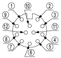
| Note: |
Input and output for pin Nos.
⑪ and ⑫ are not used by this product. |
|
|
| Connector pin No. |
Emitter side connector |
Receiver side connector |
| ① |
Interlock |
OSSD 2 |
| ② |
+24 V DC |
+24 V DC |
| ③ |
Emission halt |
OSSD 1 |
| ④ |
Auxiliary output |
EDM (External relay monitor) |
| ⑤ |
Synchronization wire + |
Synchronization wire + |
| ⑥ |
Synchronization wire – |
Synchronization wire – |
| ⑦ |
0 V |
0 V |
| ⑧ |
Shielded wire |
Shielded wire |
| ⑨ |
Interference prevention wire + |
Interference prevention wire + |
| ⑩ |
Interference prevention wire – |
Interference prevention wire – |
| ⑪ |
(Override input) |
(Muting input 1) |
| ⑫ |
(Muting lamp output) |
(Muting input 2) |
|
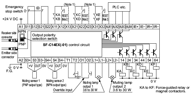
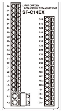
Wiring diagram of SF-C14EX(-01) and SF4B / SF4B-G series (Control Category 4)
| For PNP output (minus ground) |
- Set the output polarity selection switch to the PNP side and ground the 0 V line.
| Notes: 1) |
The above diagram is when using manual reset. If automatic reset is used, disconnect the lead from X12 and X22, and connect them to X13 and X23 as shown by the dotted lines. In this case, a reset (RESET) button is not needed. Terminals X31 to X32 are for manual reset only. |
| 2) |
Use a momentary-type switch for the reset (RESET) button. |
| For NPN output (plus ground) |
- Set the output polarity selection switch to the NPN side and ground the + side of the power supply input.
| Notes: 1) |
The left diagram is when using manual reset. If automatic reset is used, disconnect the lead from X12 and X22, and connect them to X13 and X23 as shown by the dotted lines. In this case, a reset (RESET) button is not needed. Terminals X31 to X32 are for manual reset only. |
| 2) |
Use a momentary-type switch for the reset (RESET) button. |
| ・ |
When connecting the SF-C14EX to the safety light curtains, make sure to use the following connecting cable.
SFB-CB05-EX (Cable length: 0.5 m 1.640 ft)
SFB-CB5-EX (Cable length: 5 m 16.404 ft)
SFB-CB10-EX (Cable length: 10 m 32.808 ft) |
| ・ |
If the NO (Normally Open) contact switch is used as a muting sensor,wire it as shown in the figure below.
 |
| ・ |
If the emergency stop switch is not used, short-circuit between the terminals S11 to S12 and S21 to S22 directly. |
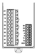
| Terminal arrangement diagram |
|
|
| Terminal |
Function |
Terminal |
Function |
| 14 |
Safety output 1, Light received
/ Light interrupted output of the safety light curtain |
S11 |
Emergency stop contact input
2 NC input
Between S11 and S12
Between S21 and S22 |
| 24 |
S12 |
| 34 |
Safety output 2, Safety light curtain output including the muting function |
S21 |
| 44 |
S22 |
| 54 |
Safety output 3 Emergency stop output |
X11 |
Safety output 1 reset input
X11 - X12: Manual reset
X11 - X13: Auto-reset |
| 64 |
X12 |
| S3+ |
Muting sensor input 1 (PNP output type)
S3+, S3–: Power supply
S3: Sensor output |
X13 |
| S3 |
X21 |
Safety output 2 reset input
X21 - X22: Manual reset
X21 - X23: Auto-reset |
| S3– |
X22 |
| S4+ |
Muting sensor input 2(NPN output type)
S4+, S4–: Power supply
S4: Sensor output |
X23 |
| S4 |
X31 |
Safety output 3 reset input
X31 - X32: Manual reset |
| S4– |
X32 |
| T1 |
Test input terminal
Open: Test mode
Short-circuit: Normal operation |
AUX1 |
Auxiliary output 1, Muting output |
| T2 |
AUX2 |
Auxiliary output 2, Override output |
| O1 |
Override input terminal
Open: Invalid
Short-circuit: Valid |
AUX3 |
Auxiliary output 3, Blown lamp output |
| O2 |
AUX4 |
Auxiliary output 4, Safety light curtain auxiliary output |
| L1+ |
Muting lamp output 1 |
IE+ |
Interference prevention terminal, Emitter side + |
| L1– |
IE– |
Interference prevention terminal, Emitter side – |
| L2+ |
Muting lamp output 2 |
IR+ |
Interference prevention terminal, Receiver side + |
| L2– |
IR– |
Interference prevention terminal, Receiver side – |
| A1 |
+24 V DC |
- |
| A2 |
0 V |
- |
|
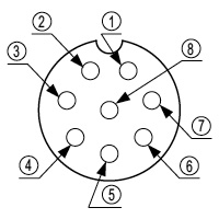
| Pin layout for light curtain connectors |
|
|
| Connector pin No. |
Emitter side connector |
Receiver side connector |
| ① |
Interference prevention wire + |
Interference prevention wire + |
| ② |
+24 V DC |
+24 V DC |
| ③ |
Interference prevention wire – |
Interference prevention wire – |
| ④ |
Auxiliary output |
Not used |
| ⑤ |
Synchronization wire + |
Synchronization wire + |
| ⑥ |
Synchronization wire – |
Synchronization wire – |
| ⑦ |
0 V |
0 V |
| ⑧ |
Shielded wire |
Shielded wire |
|
Return to top
Return to top

 Business
> Industrial Devices
> Automation Controls Top
> FA Sensors & Components
> Sensors
> Light Curtains / Safety Components
> Exclusive Control Unit for Safety Light Curtain SF-C10
> I/O Circuit and Wiring diagrams
Business
> Industrial Devices
> Automation Controls Top
> FA Sensors & Components
> Sensors
> Light Curtains / Safety Components
> Exclusive Control Unit for Safety Light Curtain SF-C10
> I/O Circuit and Wiring diagrams