[System Maintenance Notice]
Due to ongoing system maintenance, the site search and specification search functions are temporarily unavailable. We apologize for any inconvenience this may cause and appreciate your understanding.
【Notification of Manufacturer Change for Panasonic Industrial Devices SUNX Products and Panasonic Industrial Devices SUNX Tatsuno Products】
From April 1, 2024, the terms "Panasonic Industrial Devices SUNX Co., Ltd." and "Panasonic Industrial Devices SUNX Tatsuno Co., Ltd."
in this page and in the manuals and other documents to be downloaded will all be replaced with "Panasonic Industry Co., Ltd." and applied accordingly.

 Business
> Industrial Devices
> Automation Controls Top
> FA Sensors & Components
> Sensors
> Light Curtains / Safety Components
> Emergency stop switch SG-E1(Discontinued Products)
> Cautions For Use
Business
> Industrial Devices
> Automation Controls Top
> FA Sensors & Components
> Sensors
> Light Curtains / Safety Components
> Emergency stop switch SG-E1(Discontinued Products)
> Cautions For Use
Emergency stop switch SG-E1 (Discontinued Products)
|
We are sorry, the products have been discontinued. Please refer to the details of the discontinued products and the recommended substitutes list below.
|
|
Cautions For Use
- In order to avoid electric shock or fire, turn the power off before installation, removal, wire connection, maintenance, or inspection of the safety switch.
- Use wiring that is appropriate for the applied voltage and energized current, and tighten terminal screws (M3.5) to the recommended tightening torque (1.0 to 1.3 N・m). Using the switch when the screws are loose will cause it to become extremely hot, posing the risk of fire.
Mounting hole layout / minimum mounting center
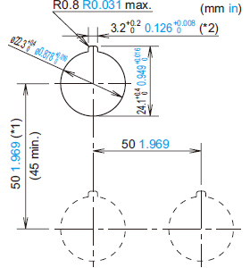 |
Note:When using the safety lever lock,determine the vertical spacing(*1) in consideration of convenience for installing and removing the safety lever lock. (Recommended vertical spacing: 100 mm 3.937 in or more) |
- The minimum mounting centers are applicable to switches with one layer of contact blocks (two contact blocks). When two layers of contact blocks are mounted, determine the minimum mounting centers in consideration of convenience for wiring.
Applicable wiring
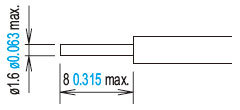
(1) The applicable wire size is 2 mm2 maximum. (single wire ø1.6 mm ø0.063 in maximum) One or two wires can be connected.
|
|
(2) Tighten the M3.5 terminal screws to a torque of 1.0 to 1.3 N・m.
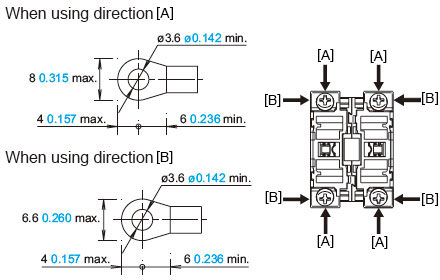
Using the lever lock
・Panasonic Industrial Devices SUNX strongly recommends using the lever lock (yellow) to prevent heavy vibration or maintenance personnel from unlocking the contact assembly.
Using SEMI guard rings
SEMI guard rings[MS-SG-GR1] are designed specifically for use with semiconductor manufacturing equipment and should not be used as emergency stop switches for machine tools, food processing machinery, or other equipment.
(The European Machinery Directive, IEC 60204-1, JIS B9960-1, and other standards require that emergency stop switches be easy to approach and operate, and use of SEMI standard-compliant switch guards is not currently approved.
|
BY EMAIL


Requests to customers (Automation Control Components & Industrial Device) [Excluding specific product]
Requests to customers (Automation Control Components & Industrial Device) [For specific product]
Requests to customers (FA Sensors & Components [Excluding motors])
Requests to customers (Dedicated to industrial motors)
- COMPONENTS & DEVICES
- FA SENSORS & COMPONENTS
- Fiber Sensors
- Photoelectric Sensors / Laser Sensors
- Micro Photoelectric Sensors
- Light Curtains / Safety Components
- Area Sensors
- Inductive Proximity Sensors
- Particular Use Sensors
- Sensor Options
- Wire-Saving Systems
- Programmable Controllers / Interface Terminal
- Human Machine Interface
- Pressure Sensors / Flow Sensors
- Measurement Sensors
- Static Control Devices
- Laser Markers / 2D Code Readers
- Machine Vision System
- Energy Management Solutions
- Timers / Counters / FA Components
- MOTORS
![]()