[System Maintenance Notice]
Due to ongoing system maintenance, the site search and specification search functions are temporarily unavailable. We apologize for any inconvenience this may cause and appreciate your understanding.
【Notification of Manufacturer Change for Panasonic Industrial Devices SUNX Products and Panasonic Industrial Devices SUNX Tatsuno Products】
From April 1, 2024, the terms "Panasonic Industrial Devices SUNX Co., Ltd." and "Panasonic Industrial Devices SUNX Tatsuno Co., Ltd."
in this page and in the manuals and other documents to be downloaded will all be replaced with "Panasonic Industry Co., Ltd." and applied accordingly.

 Business
> Industrial Devices
> Automation Controls Top
> Service & Support
> FA Technical Support
> Technical Guide (FA Sensors)
> Flow sensors
> Precautions for prorer use
Business
> Industrial Devices
> Automation Controls Top
> Service & Support
> FA Technical Support
> Technical Guide (FA Sensors)
> Flow sensors
> Precautions for prorer use
Precautions for prorer use - Flow Sensors
|
Precautions for prorer use
Flow sensor selection
- If using a flow sensor for tasks such as checking suction and release from suction nozzles and sensing leaks, use the flow rate range setting table as a guide. The effective cross-section area of the nozzle (pinhole) and the difference in pressure inside and outside the nozzle can be used to calculate the flow rate.
|
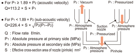
<Calculation example>
- The flow rate calculation value for a nozzle diameter of ø0.1 to ø2.0 mm ø0.004 to ø0.079 in when P2 is varied is shown in the table below.
| P1(MPa) Absolute pressure |
P1(MPa) Gauge pressure |
P2(MPa) Absolute pressure |
P2(MPa) Gauge pressure |
Acoustic velocity / Sub-acoustic velocity |
Calculated flow rate value (ℓ/min.) | |||||
|---|---|---|---|---|---|---|---|---|---|---|
| ø0.1mm ø0.004 in |
ø0.2mm ø0.008 in |
ø0.3mm ø0.012 in |
ø0.4mm ø0.016 in |
ø0.5mm ø0.020 in |
||||||
| Suction | 0.1013 | 0 | 0.0313 | -0.07 | Acoustic velocity | 0.090 | 0.360 | 0.810 | 1.440 | 2.250 |
| 0.1013 | 0 | 0.0413 | -0.06 | Acoustic velocity | 0.090 | 0.360 | 0.810 | 1.440 | 2.250 | |
| 0.1013 | 0 | 0.0513 | -0.05 | Acoustic velocity | 0.090 | 0.360 | 0.810 | 1.440 | 2.250 | |
| 0.1013 | 0 | 0.0613 | -0.04 | Sub-acoustic velocity | 0.088 | 0.352 | 0.792 | 1.408 | 2.200 | |
| 0.1013 | 0 | 0.0713 | -0.03 | Sub-acoustic velocity | 0.082 | 0.329 | 0.740 | 1.315 | 2.055 | |
| 0.1013 | 0 | 0.0813 | -0.02 | Sub-acoustic velocity | 0.072 | 0.287 | 0.645 | 1.147 | 1.792 | |
| 0.1013 | 0 | 0.0913 | -0.01 | Sub-acoustic velocity | 0.054 | 0.215 | 0.483 | 0.859 | 1.343 | |
| Blow (leakage detection) |
0.1113 | 0.01 | 0.1013 | 0 | Sub-acoustic velocity | 0.057 | 0.226 | 0.509 | 0.905 | 1.414 |
| 0.1213 | 0.02 | 0.1013 | 0 | Sub-acoustic velocity | 0.080 | 0.320 | 0.720 | 1.280 | 2.000 | |
| 0.1413 | 0.04 | 0.1013 | 0 | Sub-acoustic velocity | 0.113 | 0.453 | 1.018 | 1.810 | 2.828 | |
| 0.1613 | 0.06 | 0.1013 | 0 | Sub-acoustic velocity | 0.139 | 0.554 | 1.247 | 2.217 | 3.464 | |
| 0.1813 | 0.08 | 0.1013 | 0 | Sub-acoustic velocity | 0.160 | 0.640 | 1.440 | 2.560 | 4.000 | |
| 0.2013 | 0.1 | 0.1013 | 0 | Acoustic velocity | 0.179 | 0.716 | 1.610 | 2.862 | 4.472 | |
| 0.3013 | 0.2 | 0.1013 | 0 | Acoustic velocity | 0.268 | 1.071 | 2.410 | 4.284 | 6.694 | |
| 0.4013 | 0.3 | 0.1013 | 0 | Acoustic velocity | 0.357 | 1.426 | 3.209 | 5.706 | 8.915 | |
| 0.5013 | 0.4 | 0.1013 | 0 | Acoustic velocity | 0.445 | 1.782 | 4.009 | 7.127 | 11.137 | |
| 0.6013 | 0.5 | 0.1013 | 0 | Acoustic velocity | 0.534 | 2.137 | 4.809 | 8.549 | 13.358 | |
| P1(MPa) Absolute pressure |
P1(MPa) Gauge pressure |
P2(MPa) Absolute pressure |
P2(MPa) Gauge pressure |
Acoustic velocity / Sub-acoustic velocity |
Calculated flow rate value (ℓ/min.) | ||||
|---|---|---|---|---|---|---|---|---|---|
| ø0.7mm ø0.027 in |
ø1.0mm ø0.039 in |
ø1.5mm ø0.059 in |
ø2.0mm ø0.079 in |
||||||
| Suction | 0.1013 | 0 | 0.0313 | -0.07 | Acoustic velocity | 4.411 | 9.002 | 20.254 | 36.007 |
| 0.1013 | 0 | 0.0413 | -0.06 | Acoustic velocity | 4.411 | 9.002 | 20.254 | 36.007 | |
| 0.1013 | 0 | 0.0513 | -0.05 | Acoustic velocity | 4.411 | 9.002 | 20.254 | 36.007 | |
| 0.1013 | 0 | 0.0613 | -0.04 | Sub-acoustic velocity | 4.312 | 8.800 | 19.801 | 35.202 | |
| 0.1013 | 0 | 0.0713 | -0.03 | Sub-acoustic velocity | 4.028 | 8.220 | 18.494 | 32.878 | |
| 0.1013 | 0 | 0.0813 | -0.02 | Sub-acoustic velocity | 3.512 | 7.166 | 16.125 | 28.666 | |
| 0.1013 | 0 | 0.0913 | -0.01 | Sub-acoustic velocity | 2.631 | 5.370 | 12.083 | 21.480 | |
| Blow (leakage detection) |
0.1113 | 0.01 | 0.1013 | 0 | Sub-acoustic velocity | 2.772 | 5.657 | 12.727 | 22.626 |
| 0.1213 | 0.02 | 0.1013 | 0 | Sub-acoustic velocity | 3.920 | 8.000 | 17.999 | 31.998 | |
| 0.1413 | 0.04 | 0.1013 | 0 | Sub-acoustic velocity | 5.543 | 11.313 | 25.454 | 45.252 | |
| 0.1613 | 0.06 | 0.1013 | 0 | Sub-acoustic velocity | 6.789 | 13.856 | 31.175 | 55.423 | |
| 0.1813 | 0.08 | 0.1013 | 0 | Sub-acoustic velocity | 7.840 | 15.999 | 35.998 | 63.996 | |
| 0.2013 | 0.1 | 0.1013 | 0 | Acoustic velocity | 8.765 | 17.888 | 40.248 | 71.552 | |
| 0.3013 | 0.2 | 0.1013 | 0 | Acoustic velocity | 13.119 | 26.774 | 60.242 | 107.096 | |
| 0.4013 | 0.3 | 0.1013 | 0 | Acoustic velocity | 17.474 | 35.660 | 80.236 | 142.641 | |
| 0.5013 | 0.4 | 0.1013 | 0 | Acoustic velocity | 21.828 | 44.547 | 100.230 | 178.186 | |
| 0.6013 | 0.5 | 0.1013 | 0 | Acoustic velocity | 26.182 | 53.433 | 120.224 | 213.731 | |
| Note 1 : | In case of any leakage from tubes, etc., actual values will differ greatly from calculated values. When measuring flows, make sure that there is no leakage from any tubes. |
|---|---|
| Note 2 : | In case of any points in the tubes which are narrower than the diameter of the suction nozzle, flow rate will be restricted and may turn out to be lower than the calculated values. In addition, suction verification may not be possible in such cases. |
| Note 3 : | The effective cross-section area is a guide only. If the nozzle is long and narrow, the effective cross-section area may be smaller than the area at the tip of the nozzle. |
| Note 4 : | Response times are determined by the internal volume of the tube from the flow sensor to the suction nozzle (pinhole). If carrying out highspeed sensing, reduce the internal volume of the tube as much as possible such as by locating the flow sensor as close as possible to the suction nozzle. |
Applicable fluid
- Flow sensor is for use in air and nitrogen only. Do not use the product for other fluids since the sensing accuracy cannot be guaranteed.
- Use the clean air complied with JIS B 8392-1.1.1 to 5.6.2 and the compressed air complies with JIS B 8392-1.1.1 to 1.6.2.
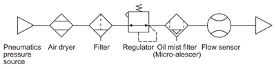
- Install a filter, an air dryer and an oil mist filter (microalescer) onto the primary side (upstream) of flow sensor since the compressed air from the compressor contains drain (water, oil oxide and foreign materials, etc.). Mesh (wire net) in the port of flow sensor is used to rectify the flow rate in the pipe. Always install a filter to flow sensor since this mesh is not a filter to remove foreign materials.
- When using a valve on the primary side of the flow sensor, only use an oil-prohibit specification valve.
Flow sensor may malfunction or break if subject to splattering grease or oil, etc.
Concerning flow rate measurement units
- The mass flow rate is measured so that the flow rate is not under the influence of temperature or pressure.
Measurement units are in ℓ/min., however this is displayed as calculated when the mass flow rate is at +20 ℃ +68 ℉, and air pressure is at 1 atm.(101 kPa).
Wring
- Make sure that the power supply is off while wiring.
- Verify that the supply voltage variation is within the rating.
- Take care that if applying voltage exceeding the rated range or connecting to AC power supply, the product may break or burn.
- If power is supplied from a commercial switching regulator, ensure that the frame ground (F.G.) terminal of the power supply is connected to an actual ground.
- Ensure that an isolation transformer is utilized for the DC power supply. If an autotransformer is utilized, the main body or power supply may be damaged
- In case noise generating equipment (switching regulator, inverter motor, etc.) is used in the vicinity of this sensor, connect the frame ground (F.G.) terminal of the equipment to an actual ground.
- If the used power supply generates a surge, connect a surge absorber to the power supply to absorb the surge.
- Do not run the wires together with high-voltage lines or power lines or put them in the same raceway. This can cause malfunction due to induction.
- In order to reduce noise, make the wiring as short as possible.
- Make sure that stress by forcible bend or pulling is not applied directly to the sensor cable joint.
Other precautions
- Our products have been developed / produced for industrial use only.
- Use within the rated flow rate range.
- Do not apply pressure exceeding the pressure withstandability value.
- Accuracy of the analogue voltage output is influenced by self-heating by applying current other than the temperature characteristics. Standby time (5 min. or more after applying current) should be taken when using the product.
- The specification may not be satisfied in a strong magnetic field.
- Avoid dust, dirt, and steam.
- Take care that if foreign materials are mixed in the sensing part, the product may break.
- Take care that the sensor does not come in direct contact with water, oil, grease, or organic solvents, such as, thinner, etc.
- Do not operate the keys with pointed or sharp objects.
- The usage environment should be within the ranges described in the specifications.
Use sensors within the range shown in the white part of the ambient temperature / humidity graph below and also within the certified ambient temperature and humidity range of each product. When using sensors within the range shown in the diagonal line shaded part of the graph, there is a possibility that condensation may occur depending on changes in the ambient temperature. Please be careful not to let this happen.
Furthermore, pay attention that freezing does not occur when using below 0 ℃ +32 ℉. Please avoid condensation and freezing when storing the product as well.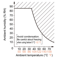
Related Products
Download
- flow_e.pdf

|
BY EMAIL


Requests to customers (Automation Control Components & Industrial Device) [Excluding specific product]
Requests to customers (Automation Control Components & Industrial Device) [For specific product]
Requests to customers (FA Sensors & Components [Excluding motors])
Requests to customers (Dedicated to industrial motors)
- COMPONENTS & DEVICES
- FA SENSORS & COMPONENTS
- Fiber Sensors
- Photoelectric Sensors / Laser Sensors
- Micro Photoelectric Sensors
- Light Curtains / Safety Components
- Area Sensors
- Inductive Proximity Sensors
- Particular Use Sensors
- Sensor Options
- Wire-Saving Systems
- Programmable Controllers / Interface Terminal
- Human Machine Interface
- Pressure Sensors / Flow Sensors
- Measurement Sensors
- Static Control Devices
- Laser Markers / 2D Code Readers
- Machine Vision System
- Energy Management Solutions
- Timers / Counters / FA Components
- MOTORS
![]()