[System Maintenance Notice]
Due to ongoing system maintenance, the site search and specification search functions are temporarily unavailable. We apologize for any inconvenience this may cause and appreciate your understanding.

 Business
> Industrial Devices
> Automation Controls Top
> Components & Devices
> Connectors
> Automotive Connectors
> CF1
> Dimensions
Business
> Industrial Devices
> Automation Controls Top
> Components & Devices
> Connectors
> Automotive Connectors
> CF1
> Dimensions
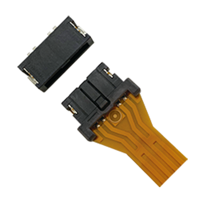
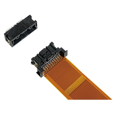
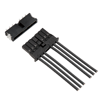
CF1
For Automotive Application with 125°C heat resistance, Connectors for board-to-FPC
|
 |

Features
- ●
Suitable for automotive applications that require vibration and heat resistance (125℃) characteristics.
- ●
“Anti-misoperation bridge structure” prevents unintended operation of mating lock.
- ●
FPCs and boards can be directly connected without relay wiring harnesses
- ●
Contact reliability is preserved by double-sided contact structure
- ●
Inertia lock construction prevents half-mating (4 pins only)
Applications
- ●
Connection of board and FPC in DRL/rear lamp
- ●
Connection of board and FPC in BMS
|
- unit: mm
1.Dimensions
Receptacle
|
|
|
Plug
|
|
|
Mating condition
|

2.Packaging Specifications
Receptacle
|
|
|
|

Plug
|
|
|
|
|
BY EMAIL


Requests to customers (Automation Control Components & Industrial Device) [Excluding specific product]
Requests to customers (Automation Control Components & Industrial Device) [For specific product]
Requests to customers (FA Sensors & Components [Excluding motors])
Requests to customers (Dedicated to industrial motors)
- COMPONENTS & DEVICES
- FA SENSORS & COMPONENTS
- Fiber Sensors
- Photoelectric Sensors / Laser Sensors
- Micro Photoelectric Sensors
- Light Curtains / Safety Components
- Area Sensors
- Inductive Proximity Sensors
- Particular Use Sensors
- Sensor Options
- Wire-Saving Systems
- Programmable Controllers / Interface Terminal
- Human Machine Interface
- Pressure Sensors / Flow Sensors
- Measurement Sensors
- Static Control Devices
- Laser Markers / 2D Code Readers
- Machine Vision System
- Energy Management Solutions
- Timers / Counters / FA Components
- MOTORS
![]()