[System Maintenance Notice]
Due to ongoing system maintenance, the site search and specification search functions are temporarily unavailable. We apologize for any inconvenience this may cause and appreciate your understanding.

 Business
> Industrial Devices
> Automation Controls Top
> Components & Devices
> Connectors
> Narrow Pitch Connectors
> S35(0.35mm pitch)
> Rating/Performance
Business
> Industrial Devices
> Automation Controls Top
> Components & Devices
> Connectors
> Narrow Pitch Connectors
> S35(0.35mm pitch)
> Rating/Performance
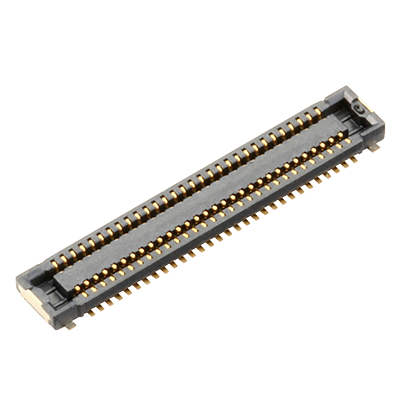
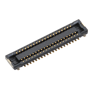
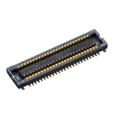
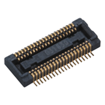
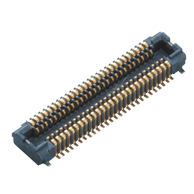
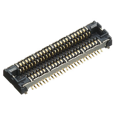
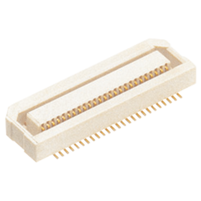
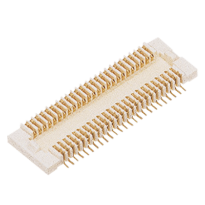
S35(0.35mm pitch)
Excellent contact reliability and mating in a super miniature size ( width 1.7 mm )
|
 |
 |

Features
- ●
Slim: width 1.7mm
- ●
Low profile construction: mated height 0.6 mm/0.8 mm
- ●
“TOUGH CONTACT” construction withstands tough environments despite being slim and low profile.
- ●
For 0.6mm mated height, thanks to our proprietary “Fine fitting” construction, high removability with a nice click feel is maintained while being low profile.
Applications
- ●
Wearable devices, smartphones and hearable devices
-
Lineup
-
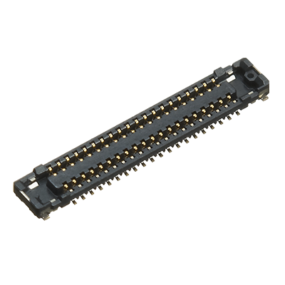
 A35S(0.35mm pitch)
Contributes to device miniaturization and advanced functionality with 2.5 mm
width, 0.35 mm pitch and 0.8 mm mated height!
A35S(0.35mm pitch)
Contributes to device miniaturization and advanced functionality with 2.5 mm
width, 0.35 mm pitch and 0.8 mm mated height!
-
 A4S(0.4mm pitch)
Being 2.5 mm in width, it facilitates ever-increasing device miniaturization and advanced functionality!
A4S(0.4mm pitch)
Being 2.5 mm in width, it facilitates ever-increasing device miniaturization and advanced functionality!
-
 F4S(0.4mm pitch)
Space-saving design with mated height of 1.0 mm and 3.6 mm width
F4S(0.4mm pitch)
Space-saving design with mated height of 1.0 mm and 3.6 mm width
-
 P4(0.4mm pitch)
Mated heights of 1.5 to 3.5 mm supported with " TOUGH CONTACT " construction to withstand of tough environments.
P4(0.4mm pitch)
Mated heights of 1.5 to 3.5 mm supported with " TOUGH CONTACT " construction to withstand of tough environments.
-
 P4S(0.4mm pitch)
High reliability, space saving type, 1.5 to 3.0 mm mated height
P4S(0.4mm pitch)
High reliability, space saving type, 1.5 to 3.0 mm mated height
-
 P4S Shield type(0.4mm pitch)
Radiation noise reduced by multi-point ground and shield construction
P4S Shield type(0.4mm pitch)
Radiation noise reduced by multi-point ground and shield construction
-
 P5K/P5KS(0.5mm pitch)
Mated heights of 3.0 to 9.0 mm supported with " TOUGH CONTACT " construction provides resistant to various environmental conditions.
P5K/P5KS(0.5mm pitch)
Mated heights of 3.0 to 9.0 mm supported with " TOUGH CONTACT " construction provides resistant to various environmental conditions.
-
 P5KF(0.5mm pitch)
0.5 mm pitch and 1.5 to 2.5 mm mated height available
P5KF(0.5mm pitch)
0.5 mm pitch and 1.5 to 2.5 mm mated height available
-
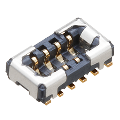 R35K(0.35mm pitch)
The ultra-small ( width 1.3 mm ) , robust yet high mating force connector that can energize 3 A.
R35K(0.35mm pitch)
The ultra-small ( width 1.3 mm ) , robust yet high mating force connector that can energize 3 A.
-
 S35(0.35mm pitch)
Excellent contact reliability and mating in a super miniature size ( width 1.7 mm )
S35(0.35mm pitch)
Excellent contact reliability and mating in a super miniature size ( width 1.7 mm )
-
- CAD data Catalogs/Datasheets
- FAQ
|
Characteristics
| Item | Specifications | Conditions | |
|---|---|---|---|
| Electrical characteristics |
Rated current | Max. 0.3 A/pin contact (Max. 5 A at total pin contacts) | |
| Rated voltage | 60 V AC/DC | ||
| Dielectric strength | 150 V AC for 1 min | No short-circuiting or damage at a detection current of 1 mA when the specified voltage is applied for 1 min | |
| Insulation resistance | Min. 1,000 MΩ (Initial) | Using 250 V DC megger (applied for 1 min) | |
| Contact resistance | Max. 90 mΩ | According to the contact resistance measurement method of JIS C 5402 | |
| Mechanical characteristics |
Composite insertion force | h = 0.6 mm 20 or less pins: Max. 26.0 N, pin contact Over 22 pins: Max. 1.300 N/pin contact x pin contacts (Initial) h = 0.8 mm Max. 1.300 N/pin contact x pin contacts (Initial) |
|
| Composite removal force | Min. 0.215 N/pin contact x pin contacts | ||
| Environmental characteristics |
Ambient temperature | -55 to +85°C | No icing. No condensation. |
| Soldering heat resistance | The initial specification must be satisfied electrically and mechanically. | Reflow soldering: Peak temperature: 260°C or less (on the surface of the PC board around the connector terminals) Soldering iron: 300°C within 5 sec. 350°C within 3 sec. |
|
| Storage temperature | -55 to +85°C (Products only) -40 to +50°C (Packaging structure) |
No icing. No condensation. | |
| Thermal shock resistance (Header and socket mated) |
5 cycles, insulation resistance: Min. 100 MΩ, contact resistance: Max. 90 mΩ |
Conformed to MIL-STD-202F, method 107G |
|
| Humidity resistance (Header and socket mated) |
120 hours, insulation resistance: Min. 100 MΩ, contact resistance: Max. 90 mΩ |
Conformed to IEC60068-2-78 Temperature 40±2°C, Humidity 90 to 95% RH |
|
| Salt water spray resistance (Header and socket mated) |
24 hours, insulation resistance: Min. 100 MΩ, contact resistance: Max. 90mΩ |
Conformed to IEC60068-2-11 Temperature 35±2°C, Salt water concentration 5±1% |
|
| H2S resistance (Header and socket mated) |
48 hours, contact resistance: Max. 90 mΩ |
Temperature 40±2°C, Gas concentration 3±1 ppm, Humidity 75 to 80% RH |
|
| Lifetime characteristics |
Insertion and removal life | 30 times | Repeated insertion and removal cycles of max. 200 times/hour |
| Unit weight | 34 pins Socket h = 0.6 mm: 0.01 g, h = 0.8 mm: 0.02 g 34 pins Header h = 0.6 mm: 0.01 g, h = 0.8 mm: 0.01 g |
||
Material and surface treatment
| Part name | Material | Surface treatment |
|---|---|---|
| Molded portion | LCP resin (UL94V-0) | — |
| Contact and Post | Copper alloy | Contact portion: Base: Ni plating, Surface: Au plating Terminal portion: Base: Ni plating, Surface: Au plating (except the terminal tips) The socket terminals close to the portion to be soldered have nickel barriers (exposed nickel portions). |
| Soldering terminals | Copper alloy | Sockets: Base: Ni plating, Surface: Pd + Au flash plating (except the terminal tips) Headers: Base: Ni plating, Surface: Au plating (except the terminal tips) |
|
Related Information
BY EMAIL


Requests to customers (Automation Control Components & Industrial Device) [Excluding specific product]
Requests to customers (Automation Control Components & Industrial Device) [For specific product]
Requests to customers (FA Sensors & Components [Excluding motors])
Requests to customers (Dedicated to industrial motors)
- COMPONENTS & DEVICES
- FA SENSORS & COMPONENTS
- Fiber Sensors
- Photoelectric Sensors / Laser Sensors
- Micro Photoelectric Sensors
- Light Curtains / Safety Components
- Area Sensors
- Inductive Proximity Sensors
- Particular Use Sensors
- Sensor Options
- Wire-Saving Systems
- Programmable Controllers / Interface Terminal
- Human Machine Interface
- Pressure Sensors / Flow Sensors
- Measurement Sensors
- Static Control Devices
- Laser Markers / 2D Code Readers
- Machine Vision System
- Energy Management Solutions
- Timers / Counters / FA Components
- MOTORS
![]()