[System Maintenance Notice]
Due to ongoing system maintenance, the site search and specification search functions are temporarily unavailable. We apologize for any inconvenience this may cause and appreciate your understanding.

 Business
> Industrial Devices
> Automation Controls Top
> Components & Devices
> Connectors
> Narrow Pitch RF Connectors
> RF35(0.35mm pitch)
> Rating/Performance
Business
> Industrial Devices
> Automation Controls Top
> Components & Devices
> Connectors
> Narrow Pitch RF Connectors
> RF35(0.35mm pitch)
> Rating/Performance
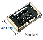
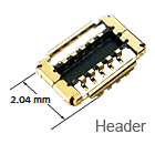
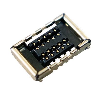
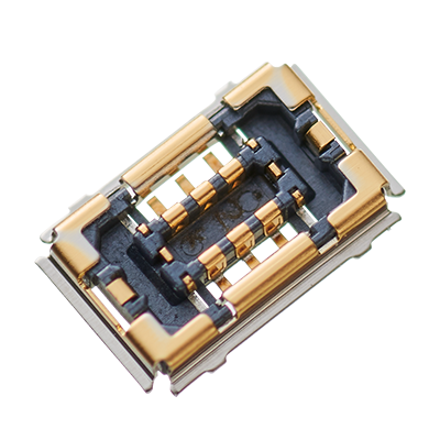
RF35(0.35mm pitch)
For 5 G Millimeter-wave Antenna Modules. 15 GHz with 5 G specifications.


Features
- ●
Good SI / EMI / EMS characteristics with high frequency application
- ●
Tough Contact structure achieves high contact reliability and high retention force
- ●
With metal exposure structure, tough against shock impact by misalignment motion or dropping
Applications
- ●
Connection between antenna module to main board 5G Millimeter-wave Antenna / UWB (Ultra Wide Band) Antenna, etc.
- ●
Smart phone / Tablet / Laptop / Router
-
Lineup
-
 RF35(0.35mm pitch)
For 5 G Millimeter-wave Antenna Modules. 15 GHz with 5 G specifications.
RF35(0.35mm pitch)
For 5 G Millimeter-wave Antenna Modules. 15 GHz with 5 G specifications.
-
 RF4(0.35mm pitch)
Compatible with 5G Millimeter-wave Antenna Modules. Excellent EMI/SI performance.
RF4(0.35mm pitch)
Compatible with 5G Millimeter-wave Antenna Modules. Excellent EMI/SI performance.
-
- CAD data Catalogs/Datasheets
- FAQ
|
Characteristics
| Item | Specifications | Conditions | |
|---|---|---|---|
| Electrical characteristics |
Rated current | Max. 0.3 A / pin contact x 8 pin contacts (signal contact) | |
| Max. 1.0 A / pin contact x 2 pin contacts (power contact) | |||
| Rated voltage | 30 V AC, DC | ||
| Dielectric strength | 150 V AC for 1 min | Detection current: 1 mA | |
| Insulation resistance | Min. 1,000 MΩ (Initial stage) | Using 250 V DC megger (applied for 1 min) | |
| Contact resistance | Max. 90 mΩ | According to the method of JIS C 5402 (Current: 1 mA) | |
| Insertion loss | DC to 10 GHz: Max. 0.30 dB 10 to 15 GHz: Max. 0.50 dB |
||
| Isolation | DC to 10 GHz: Min. 45 dB 10 to 15 GHz: Min. 35 dB |
||
| V. S. W. R | DC to 3 GHz: Max. 1.2 3 to 6 GHz: Max. 1.4 6 to 12 GHz: Max. 1.5 12 to 15 GHz: Max. 2.0 |
||
| Characteristic impedance |
50±5 Ω | ||
| Mechanical characteristics |
Composite insertion force | Max. 40 N (Initial stage) | |
| Composite removal force | Min. 2.0 N (Initial stage) | ||
| Environmental characteristics |
Ambient temperature | -50 to +85°C | No icing or condensation |
| Ambient temperature Soldering heat resistance | The initial specificaton must be satisfied electrically and mechanically | Max. peak temperature of 260 °C Infrared reflow soldering (PC board surface temperature near connector terminals) | |
| Storage temperature | -55 to +85°C (Products only) -40 to +50°C (Packaging structure) |
No icing or condensation | |
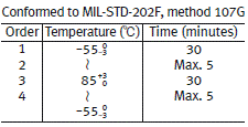
| Thermal shock resistance (header and socket mated) | After 5 cycles, Insulation resistance: Min. 100 MΩ, Contact resistance: Max. 90 mΩ |
 |
|
| Humidity resistance (header and socket mated) |
After 120 hours, Insulation resistance: Min.100 MΩ, Contact resistance: Max. 90 mΩ |
IEC60068-2-78 Temperature: 40±2°C Humidity: 90 to 95% RH |
|
| Saltwater spray resistance (header and socket mated) |
After 24 hours, Insulation resistance: Min. 100 MΩ, Contact resistance: Max. 90 mΩ |
IEC60068-2-11 Temperature: 35±2°C saltwater concentration: 5±1% |
|
| H2S resistance (header and socket mated) |
After 48 hours, Contact resistance: Max. 90 mΩ |
Temperature: 40±2°C Gas concentration: 3±1 ppm Humidity: 75 to 80% RH |
|
| Lifetime characteristics | Insertion and removal life | Mechanical life: 10 times Contact resistance: Max. 90 mΩ Composite removal force: Min. 2.0 N |
Repeated insertion and removal cycles of max. 200 times / hour |
| Unit weight | 10 contacts Soket: 0.009 g Header: 0.005 g |
||
Material and surface treatment
| Part name | Material | Surface treatment |
|---|---|---|
| Molded portion | LCP resin (UL94V-0) | - |
| Contact and Post | Copper alloy | Contact portion (main): Au plating, over nickel Contact portion (Sub): Au plating, over nickel Terminal portion: Au plating, over nickel (except for top of the terminal) Ground terminal: Au plating, over nickel (except for top of the terminal) |
|
BY EMAIL


Requests to customers (Automation Control Components & Industrial Device) [Excluding specific product]
Requests to customers (Automation Control Components & Industrial Device) [For specific product]
Requests to customers (FA Sensors & Components [Excluding motors])
Requests to customers (Dedicated to industrial motors)
- COMPONENTS & DEVICES
- FA SENSORS & COMPONENTS
- Fiber Sensors
- Photoelectric Sensors / Laser Sensors
- Micro Photoelectric Sensors
- Light Curtains / Safety Components
- Area Sensors
- Inductive Proximity Sensors
- Particular Use Sensors
- Sensor Options
- Wire-Saving Systems
- Programmable Controllers / Interface Terminal
- Human Machine Interface
- Pressure Sensors / Flow Sensors
- Measurement Sensors
- Static Control Devices
- Laser Markers / 2D Code Readers
- Machine Vision System
- Energy Management Solutions
- Timers / Counters / FA Components
- MOTORS
![]()