[System Maintenance Notice]
Due to ongoing system maintenance, the site search and specification search functions are temporarily unavailable. We apologize for any inconvenience this may cause and appreciate your understanding.

 Business
> Industrial Devices
> Automation Controls Top
> Components & Devices
> Relays / Couplers
> Solid State Relays
> Solid State Relays Lineup
> Phototriac Coupler
> Rating/Performance
Business
> Industrial Devices
> Automation Controls Top
> Components & Devices
> Relays / Couplers
> Solid State Relays
> Solid State Relays Lineup
> Phototriac Coupler
> Rating/Performance
Phototriac Coupler
-
Lineup
-
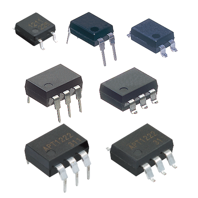 Phototriac Coupler
Phototriac coupler for the industrial machinery and consumer electronics
Phototriac Coupler
Phototriac coupler for the industrial machinery and consumer electronics
-
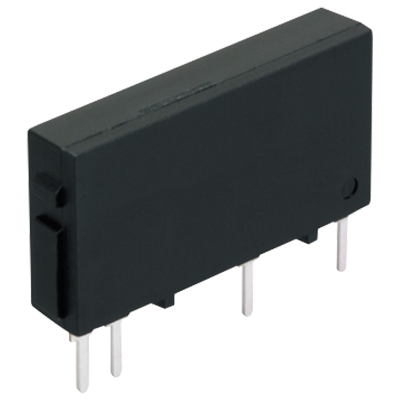
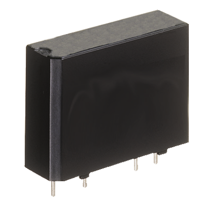 AQ1 Solid State Relay
High capacity up to 3 A/10 A PC board terminal type
AQ1 Solid State Relay
High capacity up to 3 A/10 A PC board terminal type
-
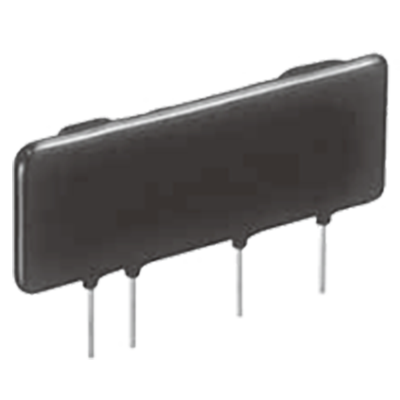 AQ8 Solid State Relay
SIL type with 9 mm thickness, 3,000 V AC high dielectric voltage, controls up to 2 A/3 A
AQ8 Solid State Relay
SIL type with 9 mm thickness, 3,000 V AC high dielectric voltage, controls up to 2 A/3 A
-
 AQ-A (AC output type) Solid State Relay
Load current up to Max. 40 A in the series, Small Screw Terminal SSR
AQ-A (AC output type) Solid State Relay
Load current up to Max. 40 A in the series, Small Screw Terminal SSR
-
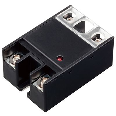 AQ-A (DC output type) Solid State Relay
Small Screw Terminal SSR Ideal for DC Control
AQ-A (DC output type) Solid State Relay
Small Screw Terminal SSR Ideal for DC Control
-
 AQ-G Solid State Relay
Slim type SSR for 1 A and 2 A control
AQ-G Solid State Relay
Slim type SSR for 1 A and 2 A control
-
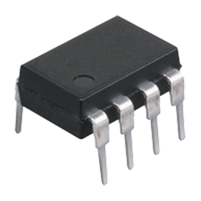 AQ-H Solid State Relay
Compact DIP type SSR Ideal for AC load control
AQ-H Solid State Relay
Compact DIP type SSR Ideal for AC load control
-
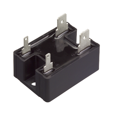 AQ-J Solid State Relay
Small tab terminal SSR, Slim heat sink combined type also available
AQ-J Solid State Relay
Small tab terminal SSR, Slim heat sink combined type also available
-
- CAD data Catalogs/Datasheets
- FAQ
|
Absolute maximum ratings (Ambient temperature: 25℃)
1.SOP4 Type
| Item | Symbol | APT1211S, APT1221S, APT1231S | Remarks | |
|---|---|---|---|---|
| Input | LED forward current | IF | 50 mA | |
| LED reverse voltage | VR | 6 V | ||
| Peak forward current | IFP | 1 A | f = 100 Hz, Duty Ratio = 0.1% |
|
| Output | Repetitive peak OFF-state voltage | VDRM | 600 V | |
| ON-state RMS current | IT (RMS) | 0.05 A | AC | |
| Non-repetitive surge current | ITSM | 0.6 A | In one cycle at 60 Hz | |
| Total power dissipation | PT | 350 mW | ||
| I/O isolation voltage | Viso | 3,750 Vrms | ||
| Ambient temperature | Topr | -40 to +100°C | Non-icing and non-condensing | |
| Storage temperature | Tstg | -40 to +125°C | Non-icing and non-condensing | |
| Junction temperature | Tj | 125°C | ||
Note: "X" at the end of the part numbers have been omitted.
2.DIP4/6 Type and DIP6 Wide terminal Type
| Item | Symbol | APT1211, APT1221, APT1231, APT1212 (W), APT1222 (W), APT1232 (W) |
Remarks | |
|---|---|---|---|---|
| Input | LED forward current | IF | 50 mA | |
| LED reverse voltage | VR | 6 V | ||
| Peak forward current | IFP | 1 A | f = 100 Hz, Duty Ratio = 0.1% |
|
| Output | Repetitive peak OFF-state voltage |
VDRM | 600 V | |
| ON-state RMS current * | IT(RMS) | 0.1 A | AC | |
| Non-repetitive surge current | ITSM | 1.2 A | In one cycle at 60 Hz | |
| Total power dissipation | PT | 500 mW | ||
| I/O isolation voltage | Viso | 5,000 Vrms | ||
| Ambient temperature | Topr | -40 to +100°C | Non-icing and non-condensing | |
| Storage temperature | Tstg | -40 to +125°C | Non-icing and non-condensing | |
| Junction temperature | Tj | 125°C | ||
| Note: | "A", "AX" and "AY" at the end of the part numbers have been omitted. |
|---|---|
| Do not exceed 0.05 A of ON state RMS current in case of following load voltage condition. DIP4pin (APT1211, APT1221, APT1231): more than 100 Vrms; DIP6pin (APT1212, APT1222, APT1232) and DIP6pin wide terminal type (APT1212W, APT1222W, APT1232W): more than 120 Vrms. |
Specifications (Ambient temperature: 25℃)
1.Zero-cross Type (Max. 50 V) , Random Type
| Item | Symbol | APT1211S APT1211 APT1212(W) |
APT1221S APT1221 APT1222(W) |
Condition | ||
|---|---|---|---|---|---|---|
| Input | LED dropout voltage | Typical | VF | 1.21 V | IF = 20 mA | |
| Maximum | 1.3 V | |||||
| LED reverse current | Typical | IR | — | VR = 6 V | ||
| Maximum | 10 µA | |||||
| Output | Repetitive peak OFF-state current |
Typical | IDRM | — | IF = 0 mA VDRM = 600 V |
|
| Maximum | 1 µA | |||||
| Repetitive peak On-state voltage |
Typical | VTM | 1.3 V | IF = 10 mA ITM = 0.05 A |
||
| Maximum | 2.5 V | |||||
| Holding current | Typical | IH | 0.3 mA | |||
| Maximum | 3.5 mA | |||||
| Critical rate of rise of OFF-state voltage |
Minimum | dv/dt | 500 V/µs | VDRM = 600 V ×1/√2 | ||
| Transfer characteristics |
Trigger LED current | Maximum | IFT | 10 mA | VD = 6 V RL = 100 Ω |
|
| Zero-cross voltage | Maximum | VZC | 50 V | — | IF = 10 mA | |
| Turn on time * | Maximum | Ton | 100 µs | IF = 20 mA VD = 6 V RL = 100 Ω |
||
| I/O capacitance | Maximum | Ciso | 1.5 pF | f = 1 MHz VB = 0 V |
||
| I/O isolation resistance | Minimum | Riso | 50 GΩ | 500 V DC | ||
Note: For type of connection, see “Schematic and wiring diagrams”.
| * | Turn on/Turn off time |
|---|
|
2.Zero-cross Type (Max. 15 V)
| Item | Symbol | APT1231S, APT1231, APT1232(W) | Condition | ||
|---|---|---|---|---|---|
| Input | LED dropout voltage | Typical | VF | 1.21 V | IF = 20 mA |
| Maximum | 1.3 V | ||||
| LED reverse current | Typical | IR | — | VR = 6 V | |
| Maximum | 10 µA | ||||
| Output | Repetitive peak OFF-state current |
Typical | IDRM | — | IF = 0 mA VDRM = 600 V |
| Maximum | 1 µA | ||||
| Repetitive peak On-state voltage |
Typical | VTM | 1.2 V | IF = 10 mA ITM = 0.03 A |
|
| Maximum | 2 V | ||||
| Holding current | Typical | IH | 0.3 mA | ||
| Maximum | 3.5 mA | ||||
| Critical rate of rise of OFF-state voltage | Minimum | dv/dt | 500 V/µs | VDRM = 600 V ×1/√2 | |
| Transfer characteristics |
Trigger LED current | Maximum | IFT | 10 mA | ITM = 0.03 A |
| Zero-cross voltage | Maximum | VZC | 15 V | IF = 10 mA | |
| Turn on time * | Maximum | Ton | 100 µs | IF = 20 mA ITM = 0.03 A |
|
| I/O capacitance | Maximum | Ciso | 1.5 pF | f = 1 MHz VB = 0 V |
|
| I/O isolation resistance | Minimum | Riso | 50 GΩ | 500 V DC | |
Note: For type of connection, see “Schematic and wiring diagrams”.
| * | Turn on/Turn off time |
|---|
|
Recommended operating conditions
Please use under recommended operating conditions to obtain expected characteristics.
| Item | Symbol | Min. | Max. | Unit |
|---|---|---|---|---|
| Input LED current | IF | 15 | 25 | mA |
|
BY EMAIL


Requests to customers (Automation Control Components & Industrial Device) [Excluding specific product]
Requests to customers (Automation Control Components & Industrial Device) [For specific product]
Requests to customers (FA Sensors & Components [Excluding motors])
Requests to customers (Dedicated to industrial motors)
- COMPONENTS & DEVICES
- FA SENSORS & COMPONENTS
- Fiber Sensors
- Photoelectric Sensors / Laser Sensors
- Micro Photoelectric Sensors
- Light Curtains / Safety Components
- Area Sensors
- Inductive Proximity Sensors
- Particular Use Sensors
- Sensor Options
- Wire-Saving Systems
- Programmable Controllers / Interface Terminal
- Human Machine Interface
- Pressure Sensors / Flow Sensors
- Measurement Sensors
- Static Control Devices
- Laser Markers / 2D Code Readers
- Machine Vision System
- Energy Management Solutions
- Timers / Counters / FA Components
- MOTORS
![]()