[System Maintenance Notice]
Due to ongoing system maintenance, the site search and specification search functions are temporarily unavailable. We apologize for any inconvenience this may cause and appreciate your understanding.

 Business
> Industrial Devices
> Automation Controls Top
> Components & Devices
> Switches
> Seal Type Switches
> Turquoise Stroke Mini Switches
> Rating/Performance
Business
> Industrial Devices
> Automation Controls Top
> Components & Devices
> Switches
> Seal Type Switches
> Turquoise Stroke Mini Switches
> Rating/Performance
Turquoise Stroke Mini Switches
-
Lineup
-
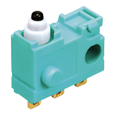
 ABJ (BJ) Turquoise Switches
Ultra-miniature Size Sealed Switches
ABJ (BJ) Turquoise Switches
Ultra-miniature Size Sealed Switches
-
 ABS (BS) Turquoise Switches
Subminiature Size Sealed Switches
ABS (BS) Turquoise Switches
Subminiature Size Sealed Switches
-
 ABV (BV) Turquoise Switches
Miniature Size Sealed Switches
ABV (BV) Turquoise Switches
Miniature Size Sealed Switches
-
 Turquoise Stroke Switches
Long Stroke and Sliding Contact Construction Sealed Switches
Turquoise Stroke Switches
Long Stroke and Sliding Contact Construction Sealed Switches
-
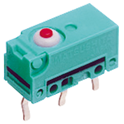
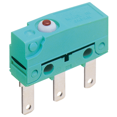
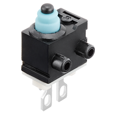
 Turquoise Stroke Mini Switches
Small size and Long Stroke Sliding Contact Construction Sealed Switches
Turquoise Stroke Mini Switches
Small size and Long Stroke Sliding Contact Construction Sealed Switches
-
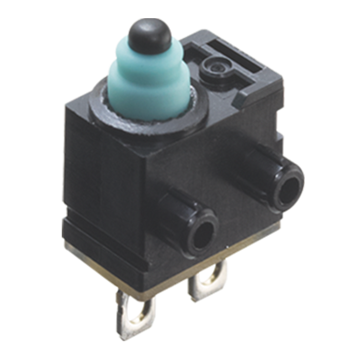
 Turquoise Stroke Mini Switch Resistor installed type
Small seal switches with wiring failure detecting function
Turquoise Stroke Mini Switch Resistor installed type
Small seal switches with wiring failure detecting function
-
- CAD data Catalogs/Datasheets
- FAQ
|
Rating
1 mA, 5 V DC to 50 mA, 16 V DC
Operation environment and conditions
| Item | Specifications |
|---|---|
| Ambient and storage temperature | –40°C to +85°C (no freezing and condensing) |
| Allowable operating speed | 30 to 500 mm/sec. |
| Max. operating cycle rate | 120 cpm |
| * | When switching at low and high speeds or under vibration, or in high-temperature, high-humidity environments, life and performance may be reduced significantly depending on the load capacity. Please consult us. |
|---|
Electrical characteristics
| Item | Specifications |
|---|---|
| Dielectric strength (Initial) | Between non-continuous terminals: 500 Vrms for 1 min Between each terminal and other exposed metal parts: 1,500 Vrms for 1 min Between each terminal and ground: 1,500 Vrms for 1 min (at detection current of 1 mA) |
| Insulation resistance (Initial) | Min. 100 MΩ (at 500 V DC insulation resistance meter) (Locations measured same as dielectric strength.) |
| Contact resistance (Initial) | Max. 500 mΩ (by voltage drop 50 mA 6 to 8 V DC) |
Characteristics
| Item | Specifications | ||
|---|---|---|---|
Electrical switching life |
5 V DC 1 mA (resistive load) |
Min. 3 × 10⁵ |
Switching frequency: 20 times/min. Conduction ratio: 1:1 Plunger operation speed: 100 mm/s Plunger switching position: Free Position (FP) to Total Travel Position (TTP) |
12 V DC 50 mA (resistive load) |
Min. 2 × 10⁵ | ||
16 V DC 50 mA (resistive load) |
Min. 1.5 × 10⁵ | ||
Vibration resistance (malfunction vibration resistance) |
Single amplitude: 0.75 mm Amplitude of vibration: 10 to 55 Hz (4 minutes cycle) Direction and time: 30 minutes each in X, Y and Z directions |
||
|
Amplitude of vibration: 5 to 200 Hz (10 minutes cycle) Acceleration: 43.1 m/s2 Direction and time: 30 minutes each in X, Y and Z directions |
|||
Shock resistance (malfunction shock resistance) |
Shock value: 980 m/s2 Direction and time: 5 times each in X, Y and Z directions |
||
Terminal strength |
Min. 6 N (each direction) *Terminal deformation possible. | ||
Heat resistance |
85°C 500 hours | ||
Cold resistance |
–40°C 500 hours | ||
Humidity resistance |
40°C 95% RH 500 hours | ||
Unit weight |
Approx. 0.5 g (Terminal type), Approx. 3.9 g (Wire leads type) | ||
Protection grade |
IP67 (Wire leads type) | ||
| * | As long as there are no particular designations, the following conditions apply to the test environment. • Ambient temperature: 5 to 35°C • Relative humidity: 25 to 85% RH • Air pressure: 86 to 106 kPa |
|---|
Protection grade
- 1.JIS C0920 (water-resistance experiments for electrical machines and protection rating against incursion of solid substances): Immersion protected *1
- 2.IEC 60529 (rating for outer shell protection): IP67 (Immersion protected) *1
except metal terminal part (See below drawing) - 3.JIS D0203 (method for testing moisture resistance and water resistance in automotive components): Equivalent of D2 *2
| *1 | A concrete testing method is to check for any adverse effect on the structure after leaving it submerged for 30 minutes under 1 m of water (with temperature difference between water and switch no larger than 5°C). |
| *2 | A concrete testing method is to check for any adverse effect on the structure after leaving it submerged for 10 minutes under 10 cm water (with temperature difference between water and switch no larger than 30°C). |
Operating characteristics
| Characteristics | Pin plunger | Simulated roller lever | |
|---|---|---|---|
| Operating Force (OF) Max. | 1.2N | 1.5N | |
| Total Travel Force (TF) Max. (Reference value) | (3.0N) | (2.8N) | |
| Free Position (FP) Max. | Terminal type | 7.7mm | 13.4mm |
| Wire leads type | 14.45mm | 20.15mm | |
| Operating Position (OP) | Terminal type | Initial: 7.1±0.25mm After test: 7.1±0.3mm |
Initial: 10.75±0.6mm After test: 10.75±0.7mm |
| Wire leads type | Initial: 13.75±0.35mm After test: 13.75±0.4mm |
Initial: 17.4±0.7mm After test: 17.4±0.8mm |
|
| Release Position (RP) | Terminal type | Initial: 7.15±0.3mm After test: 7.15±0.35mm |
Initial: 11.05±0.7mm After test: 11.05±0.8mm |
| Wire leads type | Initial: 13.8±0.4mm After test: 13.8±0.45mm |
Initial: 17.7±0.8mm After test: 17.7±0.9mm |
|
| Over Travel (OT) Min. | Terminal type | Initial: 1.75mm After test: 1.70mm |
Initial: 2.25mm After test: 2.15mm |
| Wire leads type | Initial: 1.65mm After test: 1.60mm |
Initial: 2.15mm After test: 2.05mm |
|
| Total Travel Position (TTP) (Reference value) |
Terminal type | (5.1mm) | (7.9mm) |
| Wire leads type | (11.75mm) | (14.55mm) | |
| * | The above indicates the characteristics when operating the actuator from the vertical direction. |
|---|
|
Related Information
BY EMAIL


Requests to customers (Automation Control Components & Industrial Device) [Excluding specific product]
Requests to customers (Automation Control Components & Industrial Device) [For specific product]
Requests to customers (FA Sensors & Components [Excluding motors])
Requests to customers (Dedicated to industrial motors)
- COMPONENTS & DEVICES
- FA SENSORS & COMPONENTS
- Fiber Sensors
- Photoelectric Sensors / Laser Sensors
- Micro Photoelectric Sensors
- Light Curtains / Safety Components
- Area Sensors
- Inductive Proximity Sensors
- Particular Use Sensors
- Sensor Options
- Wire-Saving Systems
- Programmable Controllers / Interface Terminal
- Human Machine Interface
- Pressure Sensors / Flow Sensors
- Measurement Sensors
- Static Control Devices
- Laser Markers / 2D Code Readers
- Machine Vision System
- Energy Management Solutions
- Timers / Counters / FA Components
- MOTORS
![]()