
 Business
> Industrial Devices
> Automation Controls Top
> Components & Devices
> Switches
> Push Switches
> ESE20C/20D Momentary Push Switches
> Cautions For Use
Business
> Industrial Devices
> Automation Controls Top
> Components & Devices
> Switches
> Push Switches
> ESE20C/20D Momentary Push Switches
> Cautions For Use
ESE20C/20D Momentary Push Switches
-
Lineup
-
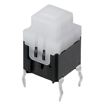 ESE20C/20D Momentary Push Switches
User friendly tactile feedback
ESE20C/20D Momentary Push Switches
User friendly tactile feedback
-
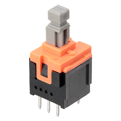 ESB30 Push Switches
Long travel
ESB30 Push Switches
Long travel
-
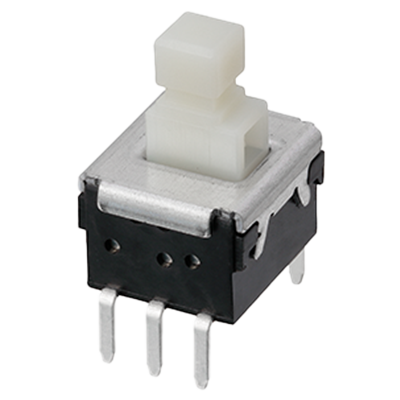 ESB33 Push Switches
Low profile, SMD
ESB33 Push Switches
Low profile, SMD
-
- CAD data Catalogs/Datasheets
- FAQ
|
Push Switches Cautions for Use
When using our Push Switches, please observe the following items ("prohibited items") and be cautious of the following in order to prevent dangerous accidents and deterioration of performance.
1.Prohibited items and notes on mounting
- 1.When soldering (including preheating), do not solder in the locked condition.
- 2.When soldering using a soldering iron, soldering conditions vary with the tip shape of the soldering iron, wat tage, and PWB thickness. Thoroughly check the con di tions in advance, including the heat resistance rat ing of the solder.
- 3.Do not apply a load to terminals when soldering. Care should be taken in this regard because a load may deteriorate electric and mechanical characteristics.
- 4.Since the push switches are not sealed, do not wash them.
- 5.When mounting a push switch to a through-hole type PWB, the infl uence of thermal stress on the switch is greater than that on one-sided PWB. Be sure to check the influence as well as the heat re sis tance rating of the solder.
2.Notes on circuit conditions
- 1.To ensure reliability, use switches within the rated range, as designated in "Product Specifi cations for Information."
- 2.To avoid malfunction of a set due to bounce generated by turning the switch ON and OFF, and/or due to chatter generated by external vibrations, etc., take the following into consideration in design.
● Read contact multiple times. (In Case of microcomputer Processing )
● Set a delay time. (Recommendation: 3 or more times of reading with the cycle of 3 ms or over)
● Prepare a CR integrating circuit. (Recommendation: A time constant of 6 ms or over ) - 3.When circuits of a two-circuit type are connected in parallel, switching timing (non-shorting, etc.) described in the specifications is not assured.
3.Prohibited items and notes on mounting and operating conditions
- 1.In principle, operate the center of the lever.
- 2.For mounting an operation button:
- 3.If multiple switches are placed side by side, or a switch is placed near another part, the gap between the switch and the adjacent switch/part must be at least 1 mm to prevent affect of flux and to ensure proper insulation distance.
- 4.Design and use so that external stress is not continuously applied to the soldering parts in a set. External stress may cause pattern peeling and solder cracks on a PWB.
- 5.When mounting a switch, check the ON/OFF position.
- 6.Contact lubricant, which is used in push switches, may flow out to the exterior of the switch due to the structure. For design review, sufficiently check the operating conditions.
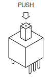
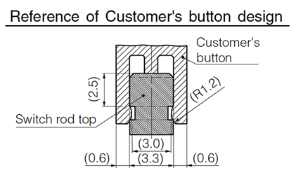
- 7.Do not pull the switch rod while it is locked. Otherwise, the self-lock ing function may be broken, resulting in a locking failure or malfunction. Make sure that the switch is released especially when attaching/detaching a button to the rod and assembling/disassembling the target product. (This applies to the self-lock ing switches) Set the strength for detach ng your button (knob) from our switch rod to a maximum of 10 N in order to minimize the possibility of a breakdown of the locking function. When designing your button, referto the following shape and dimensions.
Before adopting our switches, check the requirements carefully. - 8.Design to avoid operation with continuous lateral pressure (more than 500 mN on the lever).
- 9.Do not mount a switch by bending switch terminals.
- 10.Avoid the following ambient surroundings and other conditions because they may affect performance:
● Under an atmosphere of corrosive gas such as Cl2, H2S, NOX, or SO2
● In atmospheres of residual water drops, dew condensation, or adhesive water drops
● In liquids such as water, salt solution, oil, chem i cals, and organic solvents
● In direct sunlight
● In dusty locations
- 11.Do not apply a shock to the switch lever during mounting of the switch on the printed circuit board and installation in the target product.
1) Design so that the button is mounted to the cen ter of the lever.
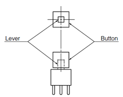
2) Design a set so that the gap (a) between the cabinet and the button is as small as possible.

3) Design so that the load in removal and mounting of the button is within the range of the switch's strength rating of the operational part.
4.Prohibited items and notes on storage conditions
Since contact characteristics and soldering quality may deteriorate due to sulfuration and oxidation of contacts and terminals, pay heed to the following items.
- 1.For storage and transport of the switches, avoid unpacking them, and store them at room tem per a ture and room humidity. Use them as soon as possible, generally within 3 months, or within a maximum of 6 months after delivery.
- 2.Do not store the switches under conditions of high temperature and/or high humidity, or in a location where corrosive gas may be generated.
- 3.If some units remain after unpacking, store them after applying adequate moisture-proof and gas-proof treat ment.
5.For use in equipment for which safety requested
Although care is taken to ensure switch quality, variation of contact resistance (increase), short circuits, open circuits, and temperature rise are some problems that might be generated. To design a set which places maximum emphasis on safety, review the affect of any single fault of a switch in advance and perform virtually fail-safe design to ensure maximum safety by
- 1.preparing a protective circuit or a protective device to improve system safety, and
- 2.preparing a redundant circuit to improve system safety so that the single fault of a switch does not cause a dangerous situation.
6.For actual use, be sure to refer to "Product Specifications for Information".
|
Related Information
BY EMAIL


Requests to customers (Automation Control Components & Industrial Device) [Excluding specific product]
Requests to customers (Automation Control Components & Industrial Device) [For specific product]
Requests to customers (FA Sensors & Components [Excluding motors])
Requests to customers (Dedicated to industrial motors)
- COMPONENTS & DEVICES
- FA SENSORS & COMPONENTS
- Fiber Sensors
- Photoelectric Sensors / Laser Sensors
- Micro Photoelectric Sensors
- Light Curtains / Safety Components
- Area Sensors
- Inductive Proximity Sensors
- Particular Use Sensors
- Sensor Options
- Wire-Saving Systems
- Programmable Controllers / Interface Terminal
- Human Machine Interface
- Pressure Sensors / Flow Sensors
- Measurement Sensors
- Static Control Devices
- Laser Markers / 2D Code Readers
- Machine Vision System
- Energy Management Solutions
- Timers / Counters / FA Components
- MOTORS
![]()