[System Maintenance Notice]
Due to ongoing system maintenance, the site search and specification search functions are temporarily unavailable. We apologize for any inconvenience this may cause and appreciate your understanding.
【Notification of Manufacturer Change for Panasonic Industrial Devices SUNX Products and Panasonic Industrial Devices SUNX Tatsuno Products】
From April 1, 2024, the terms "Panasonic Industrial Devices SUNX Co., Ltd." and "Panasonic Industrial Devices SUNX Tatsuno Co., Ltd."
in this page and in the manuals and other documents to be downloaded will all be replaced with "Panasonic Industry Co., Ltd." and applied accordingly.

 Business
> Industrial Devices
> Automation Controls Top
> FA Sensors & Components
> Timers / Counters / FA Componets
> Temperature Controllers
> KT2 Temperature Controllers
> Wiring/ Connection
Business
> Industrial Devices
> Automation Controls Top
> FA Sensors & Components
> Timers / Counters / FA Componets
> Temperature Controllers
> KT2 Temperature Controllers
> Wiring/ Connection
KT2 Temperature Controllers
|
Discontinuation plan
|
Wiring/ Connection
External Connection Diagram
|
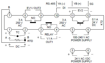
| TC | : | Input terminal for thermocouple |
|---|---|---|
| RTD | : | Input terminal for the resistance temperature detector |
| DC | : | Input terminal for DC current or DC voltage. For DC current input, connect a separately sold reception resistor (50Ω) between the input terminals. |
| OUT1 | : | Output terminal for the control output or heating output [optional: heating/cooling control]. |
| POWER SUPPLY | : | Power supply terminal. |
| EV1/OUT2 | : | Output terminal for alarm output 1 or cooling output [optional: heating/cooling control]. |
| EV2 | : | Output terminal for alarm output 2. |
| D1 | : | Input terminal for DI input (There are three types of DI input, SV1 / SV2 external switching function, OUT / OFF (RUN / STOP) external switching function, and timer function) |
| RS-485 | : | Communication terminal for serial communication. |
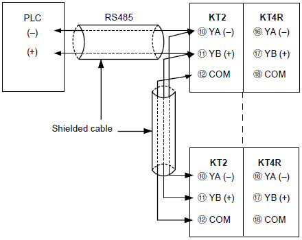
COMMUNICATION FUNCTION CONNECTION DIAGRAM (PLC Connection Diagram)
|
BY EMAIL


Requests to customers (Automation Control Components & Industrial Device) [Excluding specific product]
Requests to customers (Automation Control Components & Industrial Device) [For specific product]
Requests to customers (FA Sensors & Components [Excluding motors])
Requests to customers (Dedicated to industrial motors)
- COMPONENTS & DEVICES
- FA SENSORS & COMPONENTS
- Fiber Sensors
- Photoelectric Sensors / Laser Sensors
- Micro Photoelectric Sensors
- Light Curtains / Safety Components
- Area Sensors
- Inductive Proximity Sensors
- Particular Use Sensors
- Sensor Options
- Wire-Saving Systems
- Programmable Controllers / Interface Terminal
- Human Machine Interface
- Pressure Sensors / Flow Sensors
- Measurement Sensors
- Static Control Devices
- Laser Markers / 2D Code Readers
- Machine Vision System
- Energy Management Solutions
- Timers / Counters / FA Components
- MOTORS
![]()