[System Maintenance Notice]
Due to ongoing system maintenance, the site search and specification search functions are temporarily unavailable. We apologize for any inconvenience this may cause and appreciate your understanding.
【Notification of Manufacturer Change for Panasonic Industrial Devices SUNX Products and Panasonic Industrial Devices SUNX Tatsuno Products】
From April 1, 2024, the terms "Panasonic Industrial Devices SUNX Co., Ltd." and "Panasonic Industrial Devices SUNX Tatsuno Co., Ltd."
in this page and in the manuals and other documents to be downloaded will all be replaced with "Panasonic Industry Co., Ltd." and applied accordingly.
Digital Fiber Sensor FX-300
Partly Order Discontinued
Red LED Type
 |
February 15, 2024 |
|
|
Cautions For Use
- Never use this product as a sensing device for personnel protection.
- In case of using sensing devices for personnel protection, use products which meet laws and standards, such as OSHA, ANSI or IEC etc., for personnel protection applicable in each region or country.
| ・ |
The digital fiber sensor FX-301(P) has been modified since its production in June 2004. The explanations below are about the modified product. |
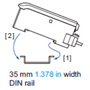
Mounting
| How to mount the amplifier |
| [1] |
Fit the rear part of the mounting section of the amplifier on a 35 mm 1.378 in width DIN rail. |
| [2] |
Press down the rear part of the mounting section of the unit on the 35 mm 1.378 in width DIN rail and fit the front part of the mounting section to the 35 mm 1.378 in width DIN rail. |
|
|
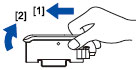
| How to remove the amplifier |
| [1] |
Push the amplifier forward. |
| [2] |
Lift up the front part of the amplifier to remove it. |
|
|
| Note: |
Take care that if the front part is lifted without pushing the amplifier forward, the hook on the rear portion of the mounting section is likely to break. |
| ・ |
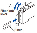
Insert the fiber into the amplifier after attaching the attachment. Refer to the "Instruction Manual" included with the fiber for details. |
| [1] |
Push the fiber lock lever down. |
| [2] |
Slowly insert the fiber into the insertion slot until it stops. (Note 1) |
| [3] |
Push the fiber lock lever back up until it stops. |
|
|
Notes:
| 1) |
Note that if the fiber is not fully inserted, the sensing distance will decrease. Also note that the flexible fiber may bend during insertion. |
| 2) |
In case of coaxial reflective type fibers (FD-G4, FD-FM2, etc.), mount the central fiber (single-core) to the emitter part and the peripheral fiber (multi-core) to the receiver. Note that sensing precision will deteriorate when done in reverse. |
Connection
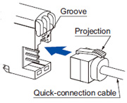
| ・ |
Make sure that the power supply is off while connecting or disconnecting the quick-connection cable. |
| [1] |
Holding the connector of the quick-connection cable, align its projection with the groove at the top portion of the amplifier connector. |
| [2] |
Insert the connector till a click is felt. |
|
|
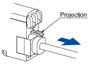
| [1] |
Pressing the projection at the top of the quick-connection cable, pull out the connector. |
|
|
| Note: |
Take care that if the connector is pulled out without pressing the projection, the projection may break. Do not use a quick-connection cable whose projection has broken. Further, do not pull by holding the cable, as this can cause a cable-break. |
Cascading
| ・ |
Make sure that the power supply is off while adding or removing the amplifiers. |
| ・ |
Make sure to check the allowable ambient temperature, as it depends on the number of amplifiers connected in cascade. |
| ・ |
In case two, or more, amplifiers are connected in cascade, make sure to mount them on a DIN rail. |
| ・ |
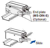
When the amplifiers move on the DIN rail depending on the attaching condition or the amplifiers are mounted close to each other in cascade, fit them between the optional end plates (MS-DIN-E) mounted at the two ends. |
| ・ |
Up to maximum 15 amplifiers can be added (total 16 amplifiers connected in cascade.) |
| ・ |
When connecting more than two amplifiers in cascade, use the sub cable (CN-71-C□ / CN-72-C□) as the quick-connection cable for the second amplifier onwards. |
| ・ |
When connecting amplifiers not close to each other in parallel, be sure to mount the optional end plate (MS-DIN-E) at both sides of each amplifier or affix the communication window seal of the accessory amplifier protection seal (FX-MB1) to the communication windows. |
| ・ |
The settings other than the interference prevention function cannot be transmitted between FX-301(P) FX-301B/G/H(P), FX-305(P). Therefore, in case both models of amplifiers are mounted in cascade, be sure to mount identical models together. However, the interference prevention function is not incorporated in the FX-301(P)-HS. Take care when the sensors are mounted in cascade. |
| ・ |
If the FX-301(P) updated version unit or the FX-305(P) is mounted with the FX-301(P) previous version unit or the FX-301B/G/H(P) in cascade, place the FX-301(P) updated version units and the FX-305(P) units to the right side (seen from the connector side) of the previous version units. For details, refer to “Cautions on sensor connection in cascade”.
For a difference between the updated version unit and the previous version unit, refer to “A difference between the updated version unit and the previous version unit”. |
| ・ |
The communication function of this product and that of the FX-301(P)-F / F7 is different. If these models are mounted in cascade, affix the accessory fiber amplifier protection seal (FX-MB1) included in the FX-301(P) and FX-305(P) to the communication windows of the amplifiers. |
| [1] |
Mount the amplifiers, one by one, on the 35 mm 1.378 in width DIN rail. |
| [2] |
Slide the amplifiers next to each other, and connect the quick-connection
cables. |
| [3] |
Mount the optional end plates (MS-DIN-E) at both the ends to hold the amplifiers between their flat sides. |
| [4] |
Tighten the screws to fix the end plates. |
|
|
| [1] |
Loosen the screws of the end plates. |
| [2] |
Remove the end plates. |
| [3] |
Slide the amplifiers and remove them one by one. |
|
|
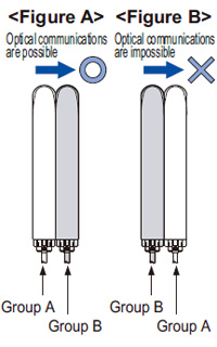
Cautions on sensor connection in cascade
- When the units in the group A and the group B shown in the table below are connected in cascade, connect them in cascade as <Figure A> shown below.
|
|
| Group A |
FX-301(P): Previous version unit (Note 1), FX-301G(P)/B(P)/H(P), FX-41□(P), LS-401(P) (Note 2) |
| Group B |
FX-301(P): Updated version unit (Note 1), FX-305(P) |
Notes:
| 1) |
For the difference between the updated version unit and the previous version unit, refer to “A difference between the updated version unit and the previous version unit”. |
| 2) |
When LS-401(P) is connected with the digital fiber amplifier in cascade, be sure to locate LS-401(P) at the left-most position (when viewed from the connector side). |
|
- When the units of the group A and the group B are connected in cascade as <Figure B> shown above, optical communications cannot be done. When the optical communications function is used, connect them as <Figure A> shown above. If the units cannot be placed as <Figure A>, the following measure [1] or [2] should be taken.
| [1] |
Affix the communication window seal of the accessory fiber amplifier protection seal (FX-MB1) to the communication window of the FX-301(P) updated version unit or FX-305(P). |
| [2] |
If the measure [1] described above cannot be taken, change the optical communications spec. of the group B units. |
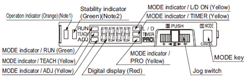
Part description
Notes:
| 1) |
FX-305(P); Output 1 operation indicator (Orange) |
| 2) |
FX-305(P); Output 2 operation indicator (Orange) |
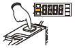
Operation procedure
- When the power supply is switched on, communication self-check is carried out and normal condition is displayed [MODE indicator / RUN (green)] lights up and the digital display shows the incident light intensity.
- When the MODE key is pressed, the mode will change as shown in the following diagram.
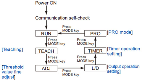 |
When Jog switch is pressed, the setting is confirmed.
When MODE key is pressed for 2 sec., or more, the sensor returns to the ‘RUN’ mode.
Cancellation is possible by pressing MODE key during setting. |
|
For FX-305(P)
The FX-305(P) is equipped with two independent outputs, but the items that can be set in output 1 and output 2 respectively are only the following.
The items other than those are common.
[1] Threshold value [2] Output operation
[3] Timer operation and Timer period [4] Sensing mode |
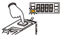
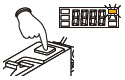
Teaching
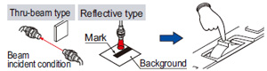
- The threshold values can be set by 2-point teaching, limit teaching, full-auto teaching or window comparator mode (1-point, 2-point, 3-point teaching) [only for FX-305(P)], when the MODE indicator / TEACH (yellow) lights up.
| In case of 2-point teaching |
- This is the method of setting the threshold value by teaching two levels, corresponding to the object present and object absent conditions. Normally, setting is done by this method.
Threshold value fine adjustment
Output operation setting
Timer operation setting
- The setting for whether the timer is used or not can be done when MODE indicator / TIMER (yellow) lights up. For FX-301B/G/H, the timer type can be set in PRO mode.
- Further, an OFF-delay (initial value) which is useful when the response of the connected device is slow, etc., an ON-delay which is useful to detect only objects taking a long time to travel, and ONE SHOT, which is useful when the input specifications of the connected device require a signal of a fixed width, are possible with the FX-301□(-HS). FX-305(P) is also equipped with ON-delay • OFF-delay and ON-delay • ONE SHOT timers. Refer to the “PRO Mode Operation Guide” for the setting method of the OFF-delay, ON-delay and ONE SHOT timer intervals.
Wiring
- Make sure that the power supply is off while wiring.
- Verify that the supply voltage variation is within the rating.
- Take care that if a voltage exceeding the rated range is applied, or if an AC power supply is directly connected, the product may get burnt or damaged.
- If power is supplied from a commercial switching regulator, ensure that the frame ground (F.G.) terminal of the power supply is connected to an actual ground.
- In case noise generating equipment (switching regulator, inverter motor, etc.) is used in the vicinity of this product, connect the frame ground (F.G.) terminal of the equipment to an actual ground.
- Take care that short circuit of the load wrong wiring may burn or damage the product.
- Do not run the wires together with high-voltage lines or power lines or put them in the same raceway. This can cause malfunction due to induction.
- Make sure to use an isolation transformer for the DC power supply. If an autotransformer (single winding transformer) is used, this product or the power supply may get damaged.
- Make sure to use the optional quick-connection cable for the connection of the amplifier. Extension up to total 100m 328.084 ft is possible with 0.3 mm2, or more, cable. (5-8 unit expansion: 50 m 164.042 ft, 9-16 unit expansion: 20 m 65.617 ft) However, in order to reduce noise, make the wiring as short as possible.
- Note that the residual voltage will increase when the cable is extended.
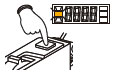
Key-lock function
- If jog switch and MODE key are pressed for more than 2 sec. at the same time in ‘RUN’ mode condition, the key operations are locked, and only the threshold value confirmation function or the adjust function (valid only when the adjust lock function is canceled) is valid. To cancel the lock function, press both the keys for more than 2 sec. once again.
| Note: |
3 seconds or more for FX-301B/G/H(P). |
Others
- When the emission halt of the light emitting amount selection function is set from “OFF” to “ON”, the output may be unstable. Do not use the output control for 0.5 sec. after starting emission.
- Do not use during the initial transient time (0.5 sec.) after the power supply is switched on.
- Take care that the sensor is not directly exposed to fluorescent lamp from a rapid-starter lamp, a high frequency lighting device or sunlight etc. , as it may affect the sensing performance.
- Do not use this sensor in places having excessive vapor, dust, etc., or where it may come in contact with corrosive gas.
- Take care that the product does not come in direct contact with water, oil, grease, or organic solvents, such as, thinner, etc.
- This sensor cannot be used in an environment containing inflammable or explosive gases.
- Never disassemble or modify the sensor.
Function table for FX-300 series
| |
Previous models |
New models |
Standard
type |
High-function
type |
High-speed
type |
Standard
type |
High-speed
type |
High-function
type |
FX-301(P)
(Previous
version unit) |
FX-302(P) |
FX-303(P) |
FX-301(P)
(Updated
version unit) |
FX-301(P)-HS |
FX-305(P) |
Four-chemical emitting
element + APC circuit |
No |
No |
No |
Yes |
Yes |
Yes |
Four-chemical
emitting element only |
Yes (Note) |
Yes |
Yes |
– |
– |
– |
Light emitting amount
selection function |
No |
No |
No |
Yes |
Yes |
Yes |
Reduced intensity mode
(S-D) |
Yes (Note) |
Yes |
No |
Yes |
Yes |
– |
| 9,999 digit display |
No |
No |
No |
No |
No |
Yes |
Response time
(Max. speed) |
150 μs |
300 μs |
90 μs |
65 μs |
35 μs |
65 μs |
Interference prevention
function (Effective no. of units) |
Incorporated (4) |
Incorporated (8) |
Not incorporated (0) |
Incorporated (4) |
Not incorporated (0) |
Incorporated (16) |
| Independent 2 outputs |
No |
No |
No |
No |
No |
Yes |
| Alarm output function |
No |
No |
No |
No |
No |
Yes |
| Error output function |
No |
No |
No |
No |
No |
Yes |
| Differential sensing |
No |
No |
No |
No |
No |
Yes |
Window comparator
mode |
No |
Yes |
No |
No |
No |
Yes |
Peripheral units that can be combined |
Bank selection unit
FX-CH(-P) |
Yes |
Yes |
No |
No |
No |
No |
External input unit
FX-CH2(-P) |
No |
No |
No |
Yes |
No |
Yes |
Upper communication unit
SC-GU1-485 |
No |
No |
No |
Yes |
No |
Yes |
| Note: |
Except FX-301B/G/H. |
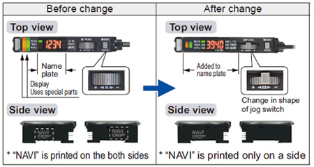
A difference between the updated version unit and the previous version unit for FX-301(P) (Red LED type)
- The product has been modified as shown below since its production in June 2004.
| ・ |
Checking minor changes between previous and updated models can be done by checking whether the printing is on both sides or only one side. |
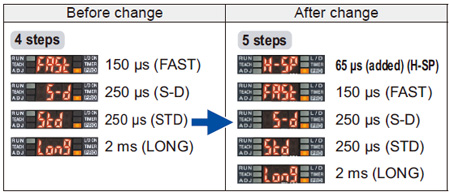
1. Response times added
| |
An ultra high-speed mode (H-SP) has been added to the existing 4 response time modes [high-speed (FAST), reduced intensity (S-D), standard (STD) and long range (LONG)].
This is changed using “ ” in “ ” in “ ” ” |
2. Extension of timer period
| |
The setting range for the timer period was previously 500 ms, but this has been extended to a new range of 9,999 ms. |
3. Light emitting amount selection function
| |
The light emitting amount can be changed to one of 4 levels (5 levels when emission halt is included). |
4. Backup, copy lock and key lock functions added
| |
| Backup: |
This selects whether or not threshold values set by teaching are written to (stored in) an EEPROM. |
| Copy lock: |
This selects whether copy function and data bank function communication are possible or not. |
| Key lock: |
This disables input using switches to prevent accidental changing of settings. |
|
1. Timer selection method
| |
| Previous version unit: |
Timer type was changed using PRO1 mode. The “TIMER” setting in NAVI mode could only be turned on or off. |
| After change: |
The type of timer can be changed using the “TIMER” function in NAVI mode. |
|
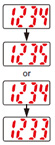
2. Checking threshold value in RUN mode
| |
The threshold values can be checked by turning the jog switch. |
1. Checking blinking of sensitivity surplus
| |
The stable surplus display method after teaching has been changed. |
| |
| |
| Previous version unit: |
Sensitivity surplus is indicated by the number of blinks of the stability indicator. |
 |
|
|
2. Initial direct code value changed
| |
The factory default settings for the direct codes have been changed. |
| |
| |
Previous version unit 0000 → After change 0004
|
| * |
The default setting for the timer period is 10 ms, and the direct code for 10 ms is “4”, so this has been changed.
|
|
1. Addition of an APC circuit
| |
A four-chemical emitting element which provides stable sensing over long periods has been added, as well as an APC ( ) circuit that improves stability during short periods. ) circuit that improves stability during short periods. |
| Cautions on sensor connection in cascade |
When connecting the previous version unit (including FX-301B/G/H) and updated version unit to be used in a cascade, refer to “Cautions on sensor connection in cascade”.
Diagram of functions and settings
The amplifier features and settings are generally classified into two main modes; the “NAVI mode” for items and settings that are frequently reconfigured, and the “PRO mode” that contains more detailed settings
Refer to product catalog or individual instruction manual for details.
>>Catalog Download site
>>Manual Download site
Return to top
Return to top

 Business
> Industrial Devices
> Automation Controls Top
> FA Sensors & Components
> Sensors
> Fiber Sensors
> Digital Fiber Sensor FX-300
> Cautions For Use
Business
> Industrial Devices
> Automation Controls Top
> FA Sensors & Components
> Sensors
> Fiber Sensors
> Digital Fiber Sensor FX-300
> Cautions For Use
 (Group A communication specification)” or “
 (Optical Communication Stop)”.
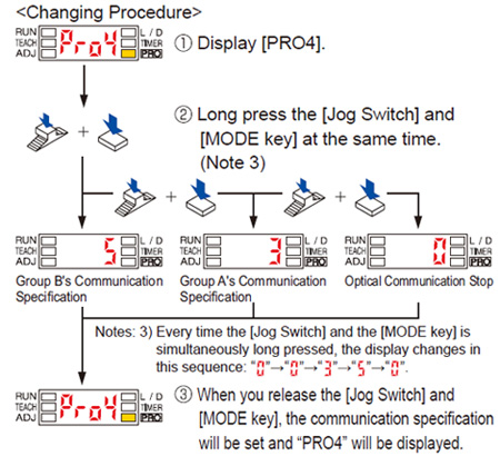

 ” or Output 2 “
 ” beforehand, press jog switch in the object present condition.


 ” is displayed.
 ” blinks.


 ” blinks in the digital display.


 ” or Output 2 “
 ” beforehand, press the jog switch continuously for 0.5 sec. or more with the object moving on the assembly line. (The incident light intensity is displayed during sampling.)
 ” is displayed on the digital display. Release the jog switch when the object has passed.
 ” is displayed.
 ” blinks.


 ” blinks in the digital display.


 ” or Output 2 “
 ” beforehand, press jog switch in the object absent condition. If the teaching is accepted, the read incident light intensity blinks in the display.
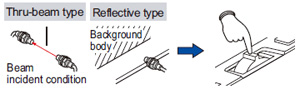


 ” blinks.
 ” blinks.


 ” blinks in the digital display.

 If jog switch is turned to the “+” side, “
 ” scrolls (twice) the display from right to left (Note 1), and the threshold level is shifted to a value approx. 15 % higher (lower sensitivity) than that set at [2]. (Note 2) This is used in case of reflective type fibers.
 If jog switch is turned to the “–” side, “
 ” scrolls (twice) the display from left to right, and the threshold level is shifted to a value approx.
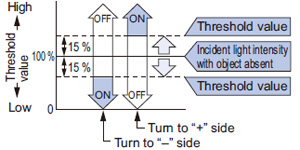


 For FX-305(P), select either Output 1 “
 ” or Output 2 “
 ” beforehand, in case the threshold value is to be increased (sensitivity to be reduced), turn the jog switch to the “+” side to increase the threshold value slowly. If the jog switch is turned continuously to the “+” side, the threshold value increases rapidly.
 In case the threshold value is to be decreased (sensitivity to be increased), turn the jog switch to the “–” side to decrease the threshold value slowly. If the jog switch is turned continuously to the “–” side, the threshold value decreases rapidly.


 ”or Output 2 “
 ” beforehand, if the jog switch is turn to the “+” or “–” direction, the output operation setting will change.