[System Maintenance Notice]
Due to ongoing system maintenance, the site search and specification search functions are temporarily unavailable. We apologize for any inconvenience this may cause and appreciate your understanding.
【Notification of Manufacturer Change for Panasonic Industrial Devices SUNX Products and Panasonic Industrial Devices SUNX Tatsuno Products】
From April 1, 2024, the terms "Panasonic Industrial Devices SUNX Co., Ltd." and "Panasonic Industrial Devices SUNX Tatsuno Co., Ltd."
in this page and in the manuals and other documents to be downloaded will all be replaced with "Panasonic Industry Co., Ltd." and applied accordingly.

 Business
> Industrial Devices
> Automation Controls Top
> FA Sensors & Components
> Sensors
> Fiber Sensors
> Color Detection Fiber Sensor FZ-10
> Cautions For Use
Business
> Industrial Devices
> Automation Controls Top
> FA Sensors & Components
> Sensors
> Fiber Sensors
> Color Detection Fiber Sensor FZ-10
> Cautions For Use
Color Detection Fiber Sensor FZ-10
Cautions For Use
Amplifier
- Never use this product as a sensing device for personnel protection.
- In case of using sensing devices for personnel protection, use products which meet laws and standards, such as OSHA, ANSI or IEC etc., for personnel protection applicable in each region or country.
Setting
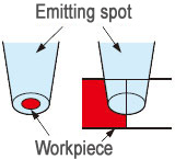
| ・ | During teaching, the FZ-10 series resolves the color projected by the spot into red, green, and blue components which are processed as numerical values and stored into the EEPROM memory. If, during teaching, the spot area is not filled by one uniform color, such as when the target objects are smaller than the spot area, or are partly projected upon, then colors other than the one you want to detect may also be sensed. Make sure that objects fill the whole spot area during teaching, as well as, sensing. The taught data is saved in the EEPROM even when the sensor power supply is switched off. However, the guaranteed rewrite operations are limited to 100,000 times because of its lifetime. |
|---|---|
| ・ | To manipulate the DIP switches, use a pair of tweezers, etc., with a tip width of 0.8 mm 0.031 in approx. |
|
|
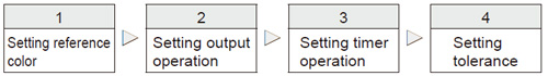
Setting tolerance
|
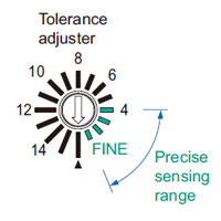
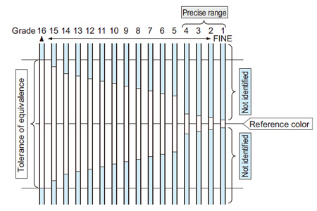
- The tolerance adjuster determines the tolerance of equivalence with respect to the reference color in 16 grades.
- Set the arrow mark of the adjuster to the desired grade from 1st to 16th using the adjusting screwdriver.
- When the grade is changed, the output is turned ON, once, for resetting.
- Even if the grade is changed, the reference color taught earlier does not change until the sensor is taught again.
- When performing auto-teaching, it is possible that teaching may fail depending upon the tolerance grade. If this happens, change the tolerance grade and repeat the teaching.
- For 16th to 5th grade, color identification is done based upon the color (red, green, blue) component ratio. For 4th to 1st grade (precise range), brightness is also considered for color identification. Hence, when the adjuster is set to the FINE side (4th to 1st grade), minute differences in gloss or color shades are also detected.
|
Others
- Do not use during the initial transient time (0.5 sec.) after the power supply is switched on.
- Periodical teaching should be done to maintain stable sensing condition.
Fiber
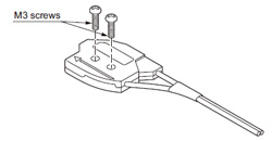
Mounting
- Mount with two M3 screws with a tightening torque of 0.5 N・m or less.
|
- Several fiber heads of FD-L51, FD-L52, FD-L53 and FD-L54 can be mounted close together as long as their emitted spots do not overlap.
Others
- If the bending radius is smaller than the allowable value, the sensing performance may deteriorate.
- Wipe dirt or stains from the sensing faces with a soft cloth. Do not use any organic solvent for cleaning.
- Ensure that any strong extraneous light is not incident on the receiving face of the fiber head.
- Do not move or bend the fiber cable after the sensitivity setting. Detection may become unstable
- Keep the fiber head surface intact. If it is scratched or spoiled, the detectability will deteriorate.
- Do not expose the fiber cable to any organic solvents.
- Ensure that the fiber head is not directly exposed to water. A water drop on the fiber head deteriorates the sensing.
- Do not apply excessive tensile force to the fiber cable.
BY EMAIL


Requests to customers (Automation Control Components & Industrial Device) [Excluding specific product]
Requests to customers (Automation Control Components & Industrial Device) [For specific product]
Requests to customers (FA Sensors & Components [Excluding motors])
Requests to customers (Dedicated to industrial motors)
- COMPONENTS & DEVICES
- FA SENSORS & COMPONENTS
- Fiber Sensors
- Photoelectric Sensors / Laser Sensors
- Micro Photoelectric Sensors
- Light Curtains / Safety Components
- Area Sensors
- Inductive Proximity Sensors
- Particular Use Sensors
- Sensor Options
- Wire-Saving Systems
- Programmable Controllers / Interface Terminal
- Human Machine Interface
- Pressure Sensors / Flow Sensors
- Measurement Sensors
- Static Control Devices
- Laser Markers / 2D Code Readers
- Machine Vision System
- Energy Management Solutions
- Timers / Counters / FA Components
- MOTORS
![]()