[System Maintenance Notice]
Due to ongoing system maintenance, the site search and specification search functions are temporarily unavailable. We apologize for any inconvenience this may cause and appreciate your understanding.
【Notification of Manufacturer Change for Panasonic Industrial Devices SUNX Products and Panasonic Industrial Devices SUNX Tatsuno Products】
From April 1, 2024, the terms "Panasonic Industrial Devices SUNX Co., Ltd." and "Panasonic Industrial Devices SUNX Tatsuno Co., Ltd."
in this page and in the manuals and other documents to be downloaded will all be replaced with "Panasonic Industry Co., Ltd." and applied accordingly.
Connector Built-in U-shaped Micro Photoelectric Sensor[Amplifier Built-in] PM-64 (Discontinued Products)
We are sorry, the products have been discontinued. Please refer to the details of the discontinued products and the recommended substitutes list below.
 |
March 31, 2017 |
|
|
Cautions For Use
- Never use this product as a sensing device for personnel protection.
- In case of using sensing devices for personnel protection, use products which meet laws and standards, such as OSHA, ANSI or IEC etc., for personnel protection applicable in each region or country.
- Make sure to connect terminals correctly as the sensor does not incorporate a reverse polarity protection circuit.
Further, the output is not incorporated with a short-circuit protection circuit. Do not connect it directly to a power supply or a capacitive load.
Faulty wiring may result in damage.
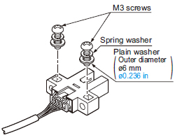
Mounting
- When fixing the sensor with screws, use M3 screws and the tightening torque should be 0.5 N·m or less.
Further, use small, round type plain washers (ø6 mm ø0.236 in).
Wiring
|
<Connector>
Housing: PAP-04V-S
(Manufactured by J.S.T.
Mfg. Co., Ltd.)
|
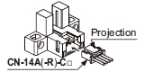
- Insert the connector attached cable CN-14A(-R)-C□ in the connector part of this product as shown in the left figure.
|
|
|
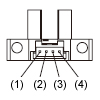
<Connector pin position>
| Connector pin No. |
Terminal designation |
| (1) |
+V |
| (2) |
Output 1 |
| (3) |
Output 2 |
| (4) |
0 V |
|
- Pressing the projection of the connector attached cable, pull out the connector.
| Note: |
Take care that if the cable is pulled out without pressing the projection, the cable may break. |
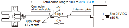
Cable extension
- Cable extension is possible up to an overall length of 100 m 328.084 ft with a 0.3 mm2, or more, cable.
However, since a voltage drop shall occur due to the cable extension, ensure that the power supply voltage at the end of the cable attached to the sensor or at the sensor terminals is within the rating.
But, when the overall cable length, including the cable attached to the sensor, is as given below, there is no need to confirm the voltage.
Conductor crosssection
area of
extension cable |
Total cable length |
| 0.08 to 0.1 mm2 |
Up to 5 m 16.404 ft |
| 0.2 mm2 |
Up to 10 m 32.808 ft |
| 0.3 mm2 |
Up to 20 m 65.617 ft |
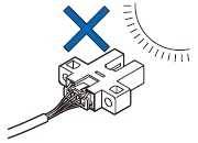
Others
- Since the sensor is intended for use inside machines, no special countermeasures have been taken against extraneous light.
Take care that extraneous light is not directly incident on the beam
receiving section.
- Do not use during the initial transient time (50 ms) after the power supply is switched on.
- If the sensor is used in a place having excessive dust, periodically clean the emitting and receiving sections with a dry, soft cloth.
- If there is a large surge generating equipment, such as, motor, solenoid, electromagnetic valve, etc., in the vicinity of the sensor, use a surge absorber on that equipment.
Further, do not run the sensor cables along power lines and use a capacitor between +V and 0 V, if required.
Use the sensor after confirming that the surge has been eliminated.
Return to top
Return to top

 Business
> Industrial Devices
> Automation Controls Top
> FA Sensors & Components
> Sensors
> Micro Photoelectric Sensors
> Connector Built-in U-shaped Micro Photoelectric Sensor[Amplifier Built-in] PM-64(Discontinued Products)
> Cautions For Use
Business
> Industrial Devices
> Automation Controls Top
> FA Sensors & Components
> Sensors
> Micro Photoelectric Sensors
> Connector Built-in U-shaped Micro Photoelectric Sensor[Amplifier Built-in] PM-64(Discontinued Products)
> Cautions For Use